Notes, worked examples and practice for this topic are being written by our tutors. The past-paper questions below are ready now: work each one on paper, then open the mark scheme and the examiner's comment.
Tap a question to zoom it. Mark scheme and examiner's comment open under each question.
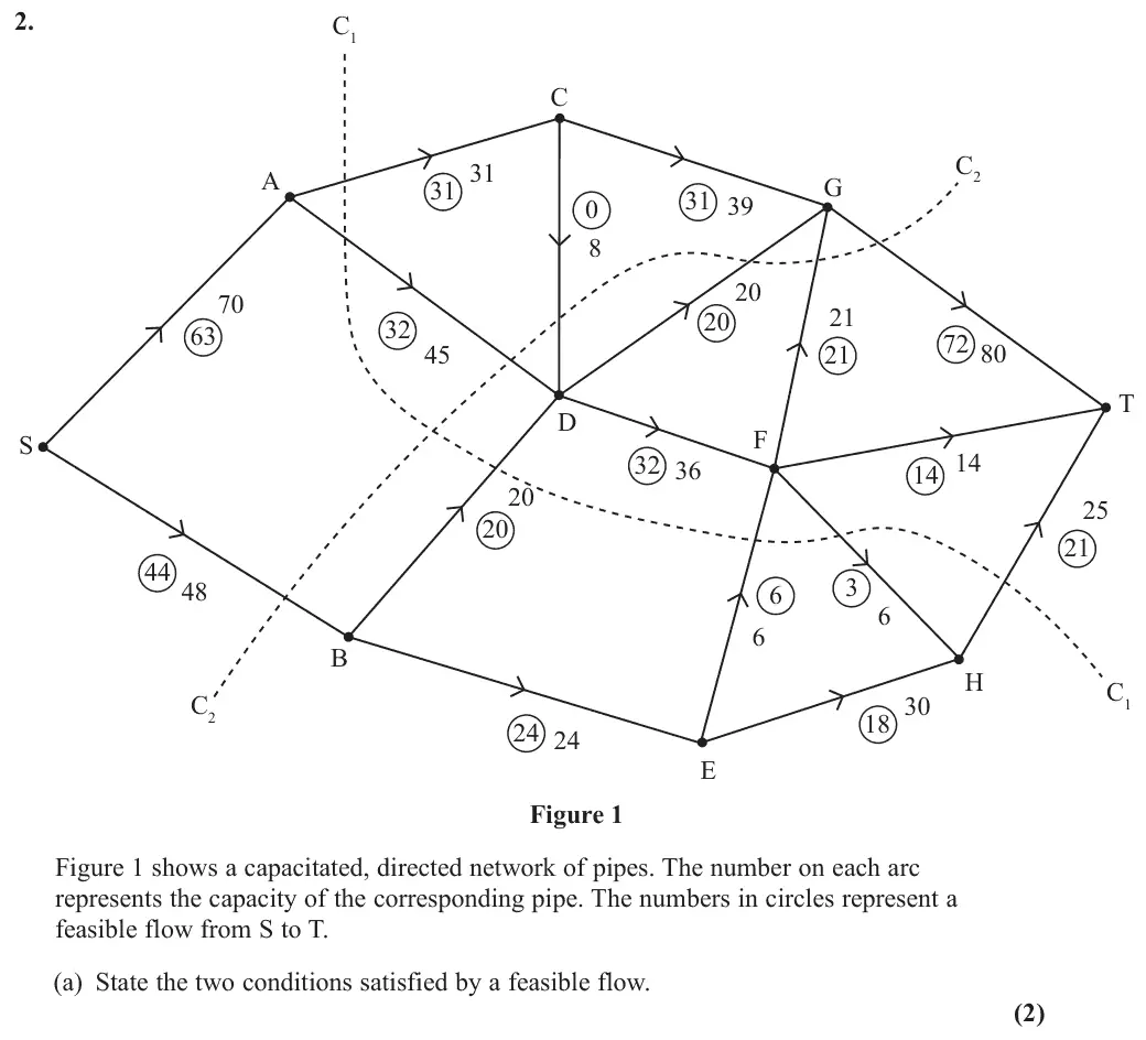
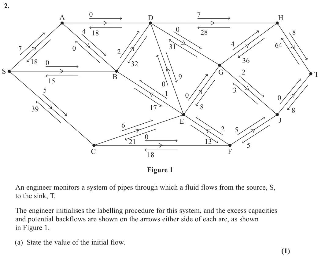
June 2025 · AS Paper 2 (Decision 2) · Q2(a)2 marks
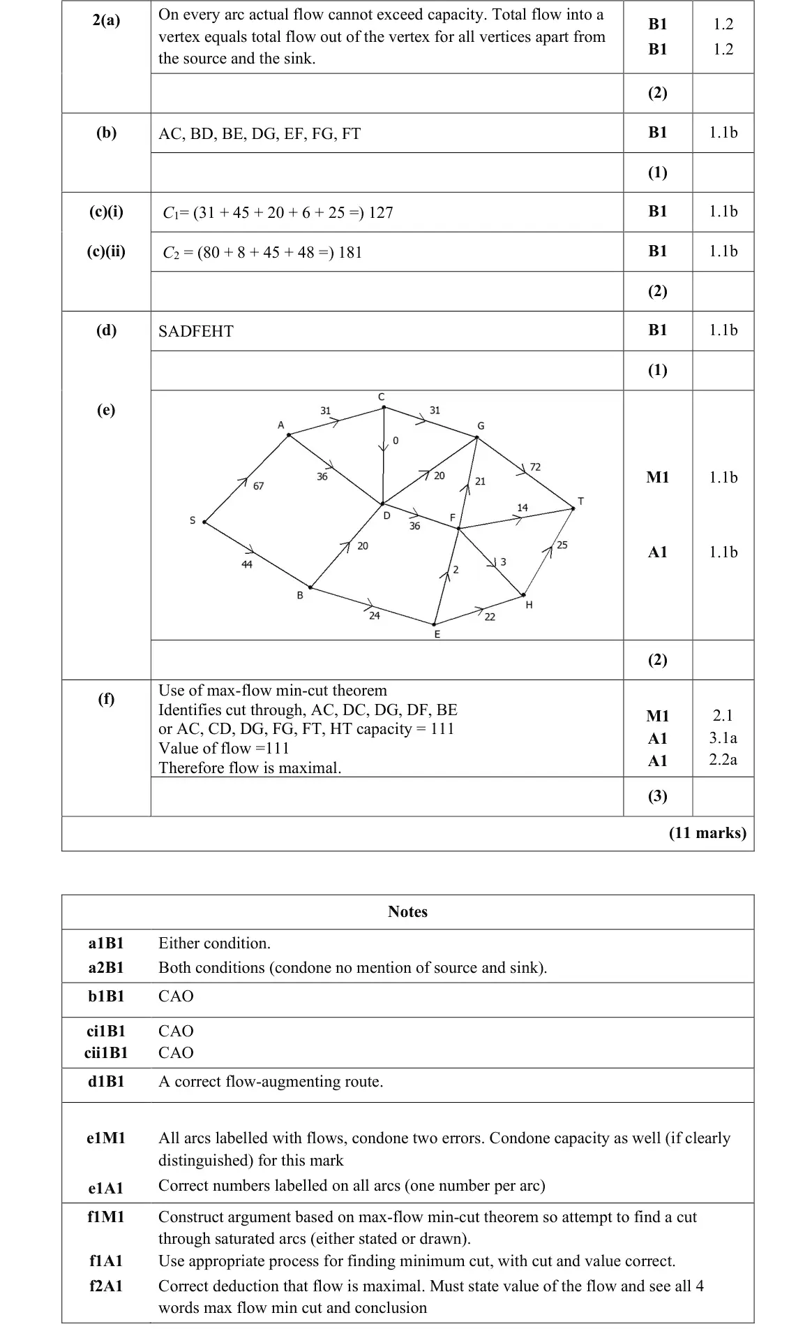
Mark scheme (whole question; this part is marked with the orange bar)
Examiner's comment
Many learners struggled to answer part (a) in sufficient detail, for example just stating “cannot exceed capacity” without relating this to the flow in an arc. Most learners listed the saturated arcs correctly and many also calculated the value of the cuts correctly, although there were some errors seen. While many learners did give the correct flow augmenting route, there was a significant minority who failed to find this. As a consequence, there were a number of errors seen with the final flow diagram and some learners did not attempt this. Those learners who did attempt the final flow diagram generally went on to attempt to prove that the flow was maximal by finding a cut through saturated arcs. However, there were a number of errors seen, either with an incorrect cut, not stating the value of the cut or flow or failing to write the conclusion that, due to the Maximum Flow – Minimum Cut theorem the flow is maximal.
Key points from the mark scheme and examiner's report
flow in each arc cannot exceed its capacity
flow in = flow out at every vertex except S and T
'cannot exceed capacity' without referring to arcs was common
June 2025 · AS Paper 2 (Decision 2) · Q2(b)1 mark
Mark scheme (whole question; this part is marked with the orange bar)
Examiner's comment
Many learners struggled to answer part (a) in sufficient detail, for example just stating “cannot exceed capacity” without relating this to the flow in an arc. Most learners listed the saturated arcs correctly and many also calculated the value of the cuts correctly, although there were some errors seen. While many learners did give the correct flow augmenting route, there was a significant minority who failed to find this. As a consequence, there were a number of errors seen with the final flow diagram and some learners did not attempt this. Those learners who did attempt the final flow diagram generally went on to attempt to prove that the flow was maximal by finding a cut through saturated arcs. However, there were a number of errors seen, either with an incorrect cut, not stating the value of the cut or flow or failing to write the conclusion that, due to the Maximum Flow – Minimum Cut theorem the flow is maximal.
Key points from the mark scheme and examiner's report
AC, BD, BE, DG, EF, FG, FT
June 2025 · AS Paper 2 (Decision 2) · Q2(c)2 marks
Mark scheme (whole question; this part is marked with the orange bar)
Examiner's comment
Many learners struggled to answer part (a) in sufficient detail, for example just stating “cannot exceed capacity” without relating this to the flow in an arc. Most learners listed the saturated arcs correctly and many also calculated the value of the cuts correctly, although there were some errors seen. While many learners did give the correct flow augmenting route, there was a significant minority who failed to find this. As a consequence, there were a number of errors seen with the final flow diagram and some learners did not attempt this. Those learners who did attempt the final flow diagram generally went on to attempt to prove that the flow was maximal by finding a cut through saturated arcs. However, there were a number of errors seen, either with an incorrect cut, not stating the value of the cut or flow or failing to write the conclusion that, due to the Maximum Flow – Minimum Cut theorem the flow is maximal.
Key points from the mark scheme and examiner's report
Mark scheme (whole question; this part is marked with the orange bar)
Examiner's comment
Many learners struggled to answer part (a) in sufficient detail, for example just stating “cannot exceed capacity” without relating this to the flow in an arc. Most learners listed the saturated arcs correctly and many also calculated the value of the cuts correctly, although there were some errors seen. While many learners did give the correct flow augmenting route, there was a significant minority who failed to find this. As a consequence, there were a number of errors seen with the final flow diagram and some learners did not attempt this. Those learners who did attempt the final flow diagram generally went on to attempt to prove that the flow was maximal by finding a cut through saturated arcs. However, there were a number of errors seen, either with an incorrect cut, not stating the value of the cut or flow or failing to write the conclusion that, due to the Maximum Flow – Minimum Cut theorem the flow is maximal.
Key points from the mark scheme and examiner's report
SADFEHT, using the backflow on EF
a significant minority could not find it
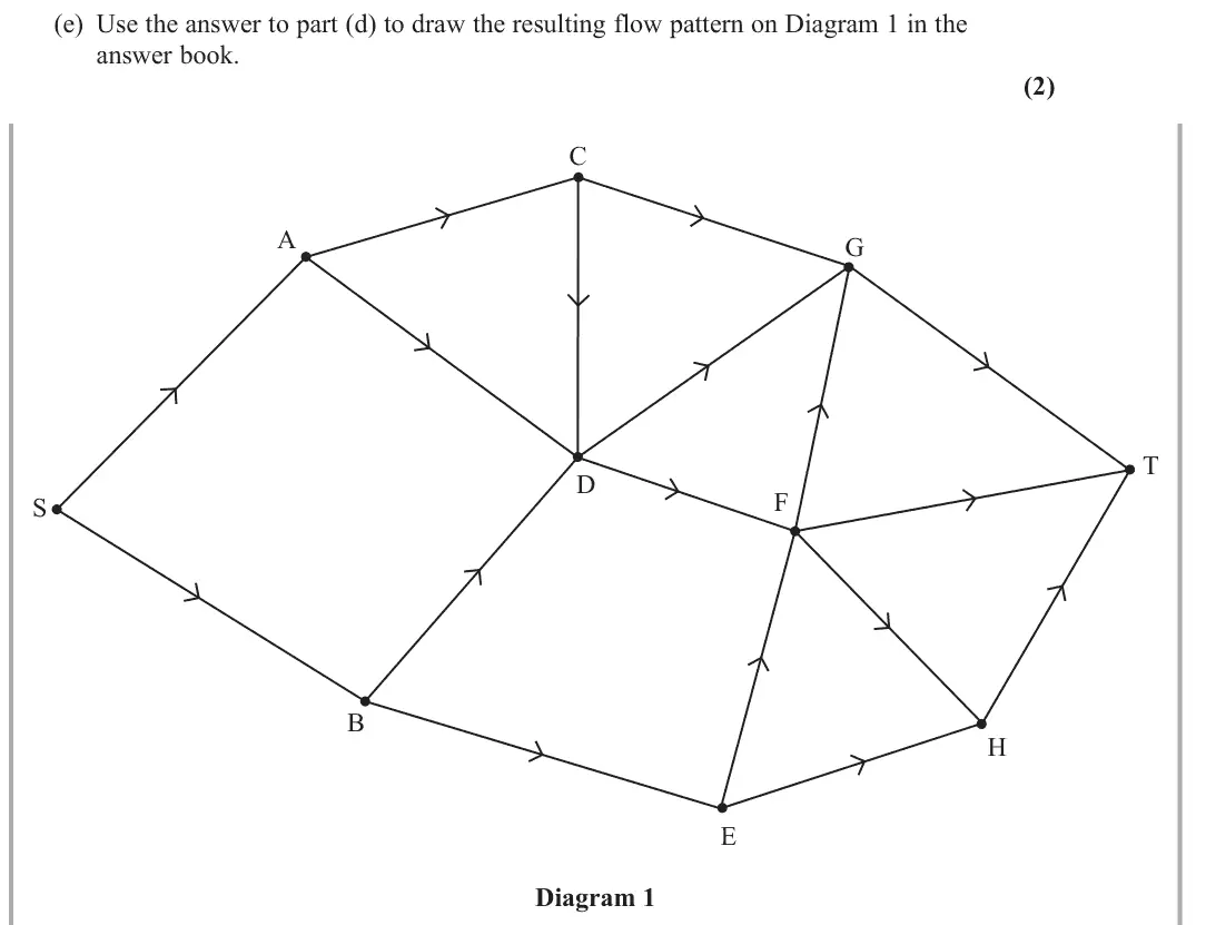
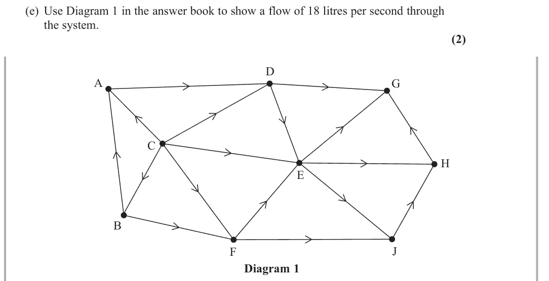
June 2025 · AS Paper 2 (Decision 2) · Q2(e)2 marks
Mark scheme (whole question; this part is marked with the orange bar)
Examiner's comment
Many learners struggled to answer part (a) in sufficient detail, for example just stating “cannot exceed capacity” without relating this to the flow in an arc. Most learners listed the saturated arcs correctly and many also calculated the value of the cuts correctly, although there were some errors seen. While many learners did give the correct flow augmenting route, there was a significant minority who failed to find this. As a consequence, there were a number of errors seen with the final flow diagram and some learners did not attempt this. Those learners who did attempt the final flow diagram generally went on to attempt to prove that the flow was maximal by finding a cut through saturated arcs. However, there were a number of errors seen, either with an incorrect cut, not stating the value of the cut or flow or failing to write the conclusion that, due to the Maximum Flow – Minimum Cut theorem the flow is maximal.
Key points from the mark scheme and examiner's report
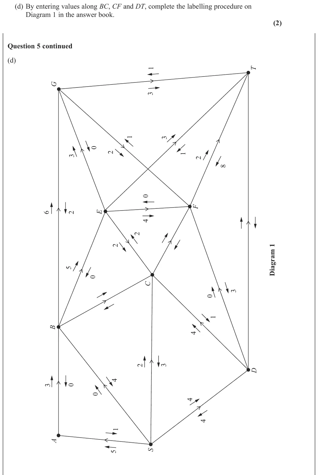
flow of 111 on Diagram 1: one number on every arc (e.g. SA 67, AD 36, DF 36, EF 2, FH 3, EH 22, HT 25)
June 2025 · AS Paper 2 (Decision 2) · Q2(f)3 marks
Mark scheme (whole question; this part is marked with the orange bar)
Examiner's comment
Many learners struggled to answer part (a) in sufficient detail, for example just stating “cannot exceed capacity” without relating this to the flow in an arc. Most learners listed the saturated arcs correctly and many also calculated the value of the cuts correctly, although there were some errors seen. While many learners did give the correct flow augmenting route, there was a significant minority who failed to find this. As a consequence, there were a number of errors seen with the final flow diagram and some learners did not attempt this. Those learners who did attempt the final flow diagram generally went on to attempt to prove that the flow was maximal by finding a cut through saturated arcs. However, there were a number of errors seen, either with an incorrect cut, not stating the value of the cut or flow or failing to write the conclusion that, due to the Maximum Flow – Minimum Cut theorem the flow is maximal.
Key points from the mark scheme and examiner's report
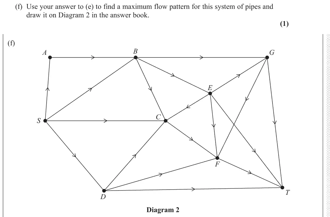
cut through AC, DC, DG, DF, BE (or AC, CD, DG, FG, FT, HT) has capacity 111 = flow
state the flow value and max flow = min cut with a conclusion
wrong cuts and missing conclusions common
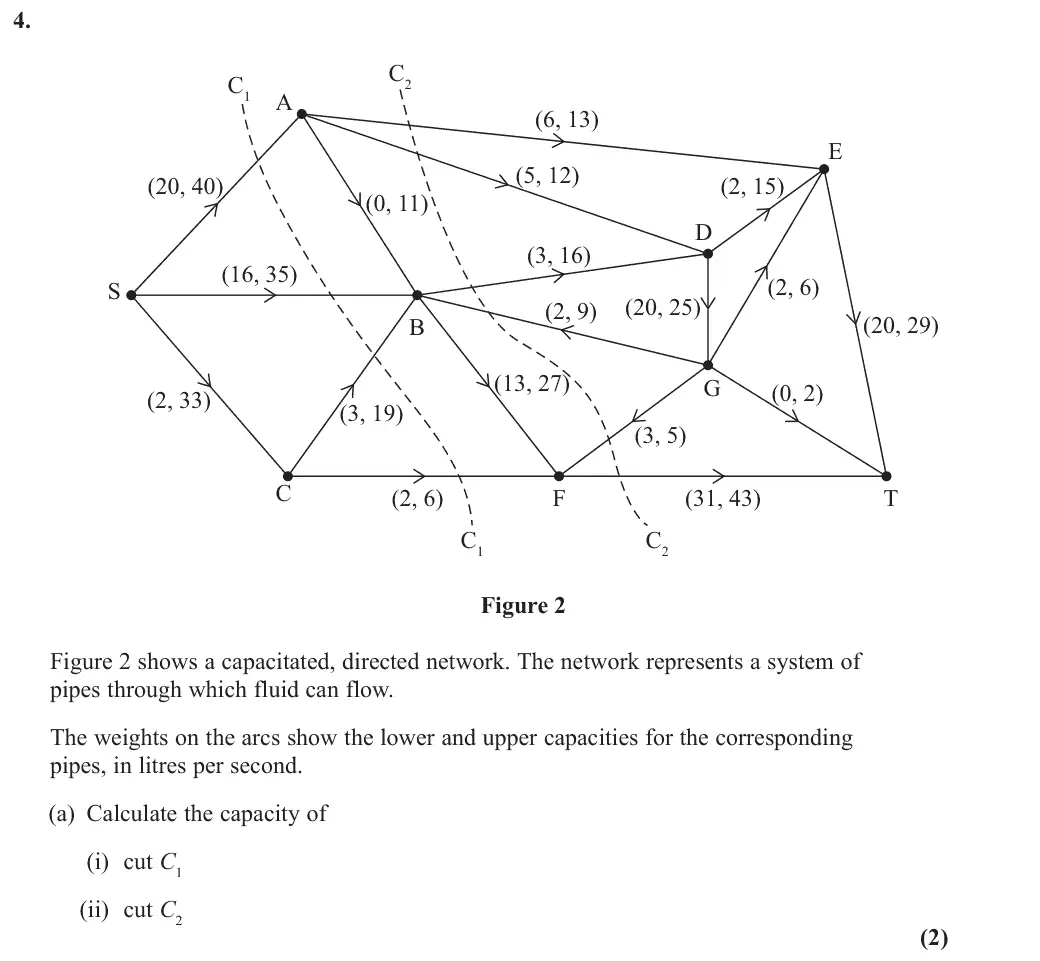
June 2025 · Paper 4D (Decision 2) · Q4(a)2 marks
Mark scheme (whole question; this part is marked with the orange bar)
Examiner's comment
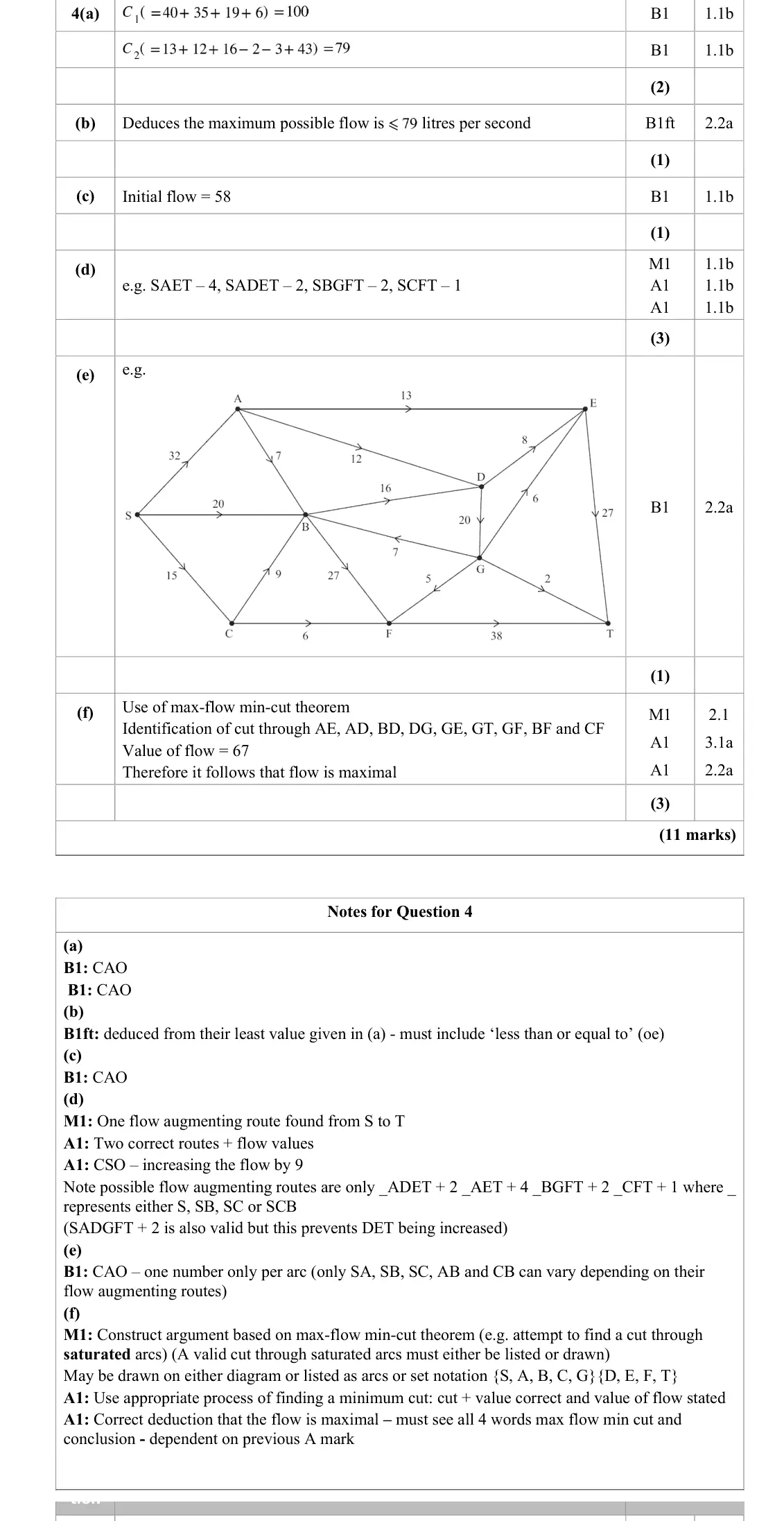
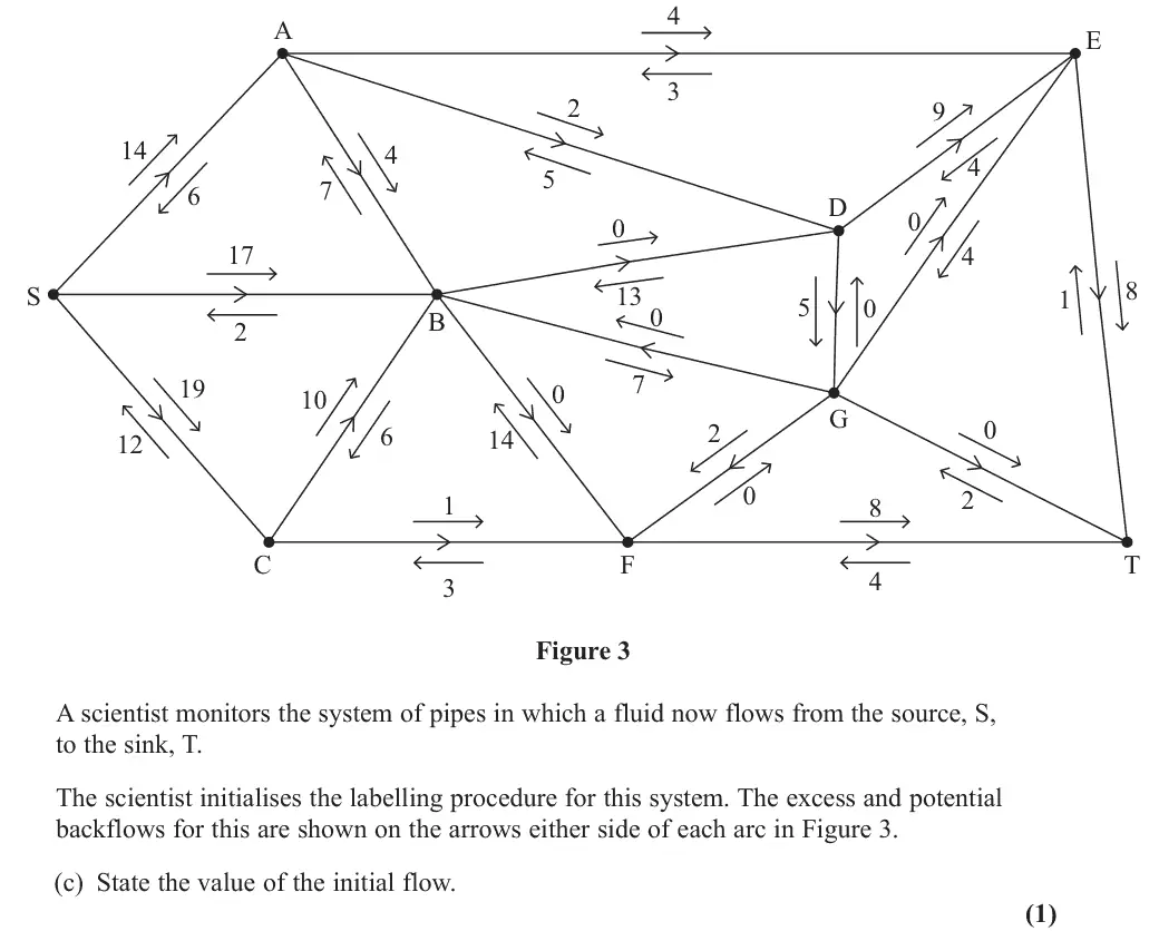
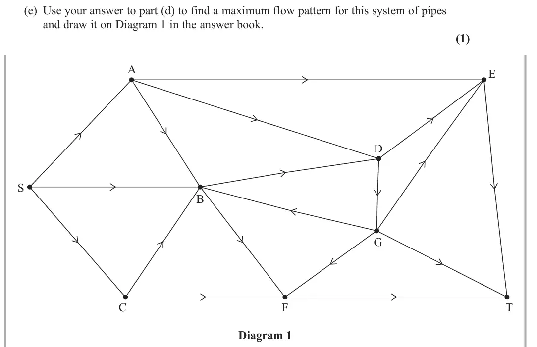
A significant number of candidates struggled to answer this question well. While a good number of candidates calculated the value of cut C1 correctly, many did not calculate C2 correctly. Most candidates related the maximum value of the flow to the smaller value of their cuts, but some incorrectly stated that it was equal to this, rather than less than or equal to the value. Some candidates were able to deduce the value of the initial flow, but a significant number failed to do so. Most candidates were able to find at least two correct flow augmenting routes, although relatively few found all four and the correct final flow of 67. Very few candidates drew a correct final flow diagram and relatively few even attempted to prove that their flow was maximal. Of those that did attempt this, only some were able to build a complete argument that this was true.
Key points from the mark scheme and examiner's report
Mark scheme (whole question; this part is marked with the orange bar)
Examiner's comment
A significant number of candidates struggled to answer this question well. While a good number of candidates calculated the value of cut C1 correctly, many did not calculate C2 correctly. Most candidates related the maximum value of the flow to the smaller value of their cuts, but some incorrectly stated that it was equal to this, rather than less than or equal to the value. Some candidates were able to deduce the value of the initial flow, but a significant number failed to do so. Most candidates were able to find at least two correct flow augmenting routes, although relatively few found all four and the correct final flow of 67. Very few candidates drew a correct final flow diagram and relatively few even attempted to prove that their flow was maximal. Of those that did attempt this, only some were able to build a complete argument that this was true.
Key points from the mark scheme and examiner's report
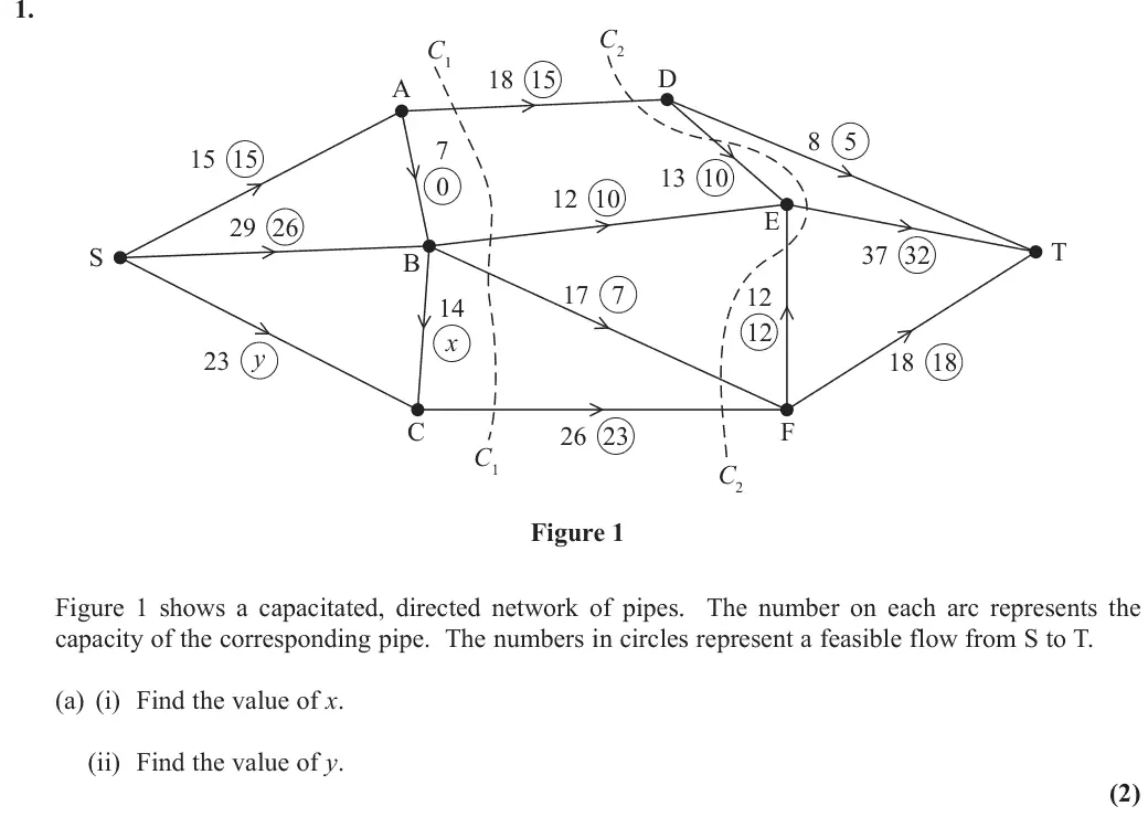
maximum flow ≤ 79
must say 'less than or equal to', not 'equal to'
June 2025 · Paper 4D (Decision 2) · Q4(c)1 mark
Mark scheme (whole question; this part is marked with the orange bar)
Examiner's comment
A significant number of candidates struggled to answer this question well. While a good number of candidates calculated the value of cut C1 correctly, many did not calculate C2 correctly. Most candidates related the maximum value of the flow to the smaller value of their cuts, but some incorrectly stated that it was equal to this, rather than less than or equal to the value. Some candidates were able to deduce the value of the initial flow, but a significant number failed to do so. Most candidates were able to find at least two correct flow augmenting routes, although relatively few found all four and the correct final flow of 67. Very few candidates drew a correct final flow diagram and relatively few even attempted to prove that their flow was maximal. Of those that did attempt this, only some were able to build a complete argument that this was true.
Key points from the mark scheme and examiner's report
initial flow 58 (from the backflow arrows into T or out of S)
many could not deduce it
June 2025 · Paper 4D (Decision 2) · Q4(d)3 marks
Mark scheme (whole question; this part is marked with the orange bar)
Examiner's comment
A significant number of candidates struggled to answer this question well. While a good number of candidates calculated the value of cut C1 correctly, many did not calculate C2 correctly. Most candidates related the maximum value of the flow to the smaller value of their cuts, but some incorrectly stated that it was equal to this, rather than less than or equal to the value. Some candidates were able to deduce the value of the initial flow, but a significant number failed to do so. Most candidates were able to find at least two correct flow augmenting routes, although relatively few found all four and the correct final flow of 67. Very few candidates drew a correct final flow diagram and relatively few even attempted to prove that their flow was maximal. Of those that did attempt this, only some were able to build a complete argument that this was true.
Key points from the mark scheme and examiner's report
e.g. SAET 4, SADET 2, SBGFT 2, SCFT 1: increase of 9 to 67
few found all four routes
June 2025 · Paper 4D (Decision 2) · Q4(e)1 mark
Mark scheme (whole question; this part is marked with the orange bar)
Examiner's comment
A significant number of candidates struggled to answer this question well. While a good number of candidates calculated the value of cut C1 correctly, many did not calculate C2 correctly. Most candidates related the maximum value of the flow to the smaller value of their cuts, but some incorrectly stated that it was equal to this, rather than less than or equal to the value. Some candidates were able to deduce the value of the initial flow, but a significant number failed to do so. Most candidates were able to find at least two correct flow augmenting routes, although relatively few found all four and the correct final flow of 67. Very few candidates drew a correct final flow diagram and relatively few even attempted to prove that their flow was maximal. Of those that did attempt this, only some were able to build a complete argument that this was true.
Key points from the mark scheme and examiner's report
flow of 67, one number per arc, consistent at every vertex and within the (lower, upper) bounds
very few drew a correct diagram
June 2025 · Paper 4D (Decision 2) · Q4(f)3 marks
Mark scheme (whole question; this part is marked with the orange bar)
Examiner's comment
A significant number of candidates struggled to answer this question well. While a good number of candidates calculated the value of cut C1 correctly, many did not calculate C2 correctly. Most candidates related the maximum value of the flow to the smaller value of their cuts, but some incorrectly stated that it was equal to this, rather than less than or equal to the value. Some candidates were able to deduce the value of the initial flow, but a significant number failed to do so. Most candidates were able to find at least two correct flow augmenting routes, although relatively few found all four and the correct final flow of 67. Very few candidates drew a correct final flow diagram and relatively few even attempted to prove that their flow was maximal. Of those that did attempt this, only some were able to build a complete argument that this was true.
Key points from the mark scheme and examiner's report
max-flow min-cut theorem: cut through AE, AD, BD, DG, GE, GT, GF, BF, CF, i.e. {S, A, B, C, G} and {D, E, F, T}, capacity 67 = flow 67, so maximal
must use all four words max flow min cut
rarely attempted
June 2024 · AS Paper 2 (Decision 2) · Q1(a)1 mark
Mark scheme (whole question; this part is marked with the orange bar)
Examiner's comment
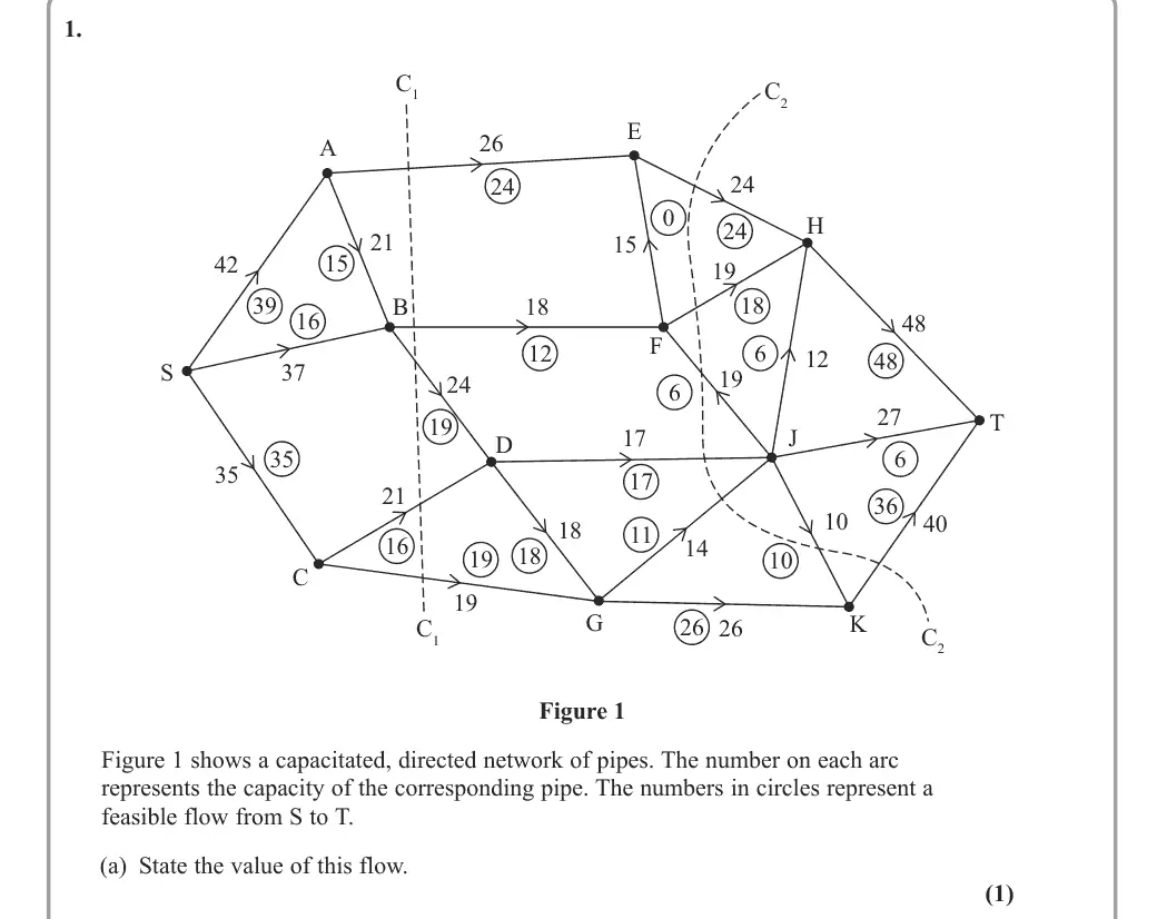
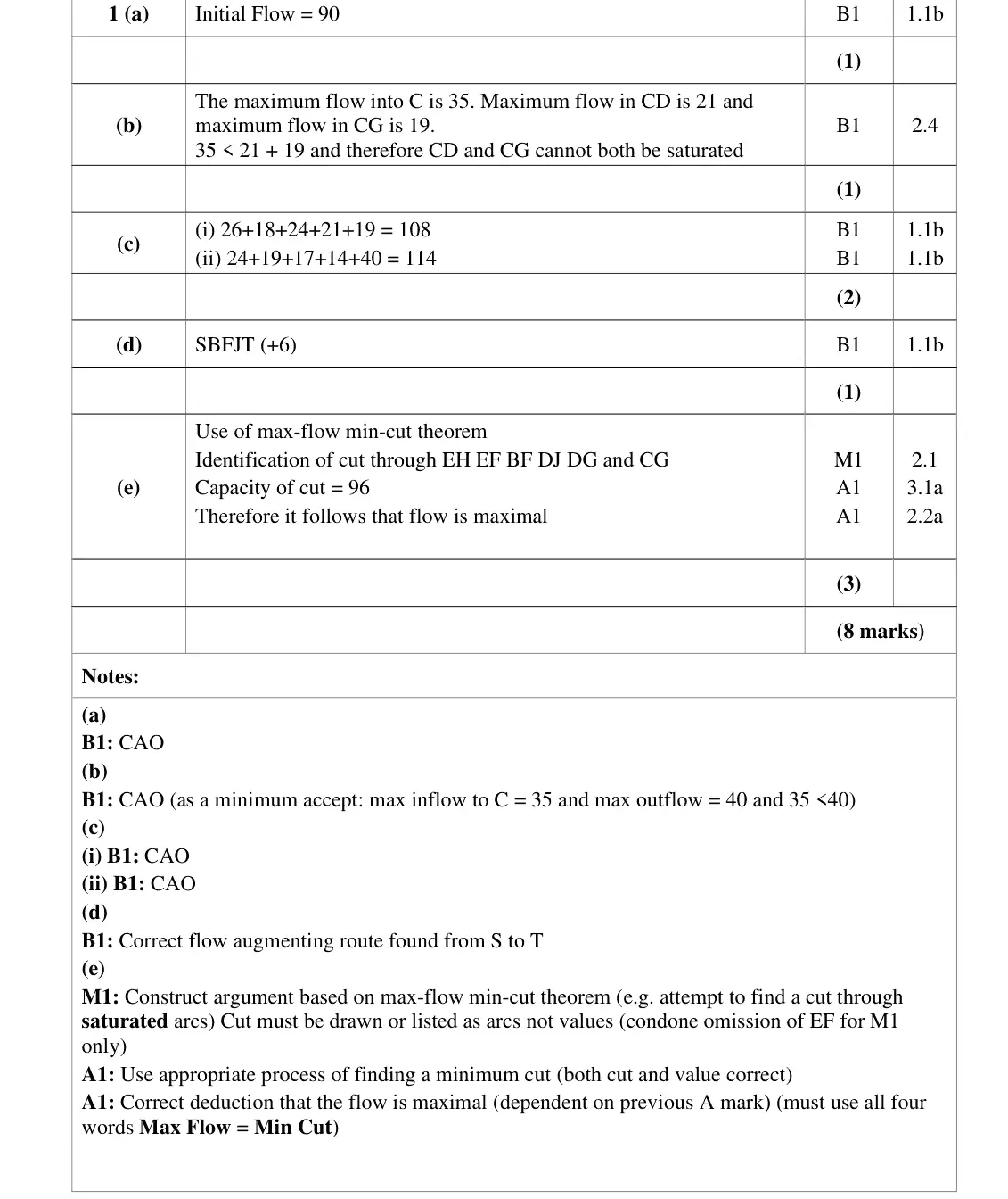
Most candidates found this question accessible and were able to answer at least some parts. Most calculated the initial flow correctly and then recognised that the capacity of SC (35) could not saturate the two arcs connected to it as their combined capacities totalled 40. However, some failed to mention that the flow of 35 was the maximum or did not compare 35 and 40 or did not give values for the capacities at all. A few focused on the flow beyond C without mention of the flow into C. Most candidates calculated the correct value for the first cut, but a number made errors with the, more complicated, second cut. Many candidates found the correct flow augmenting route, although some incorrectly tried to increase the flow in JH or HT. Although most candidates had a general idea of the maximum flow minimum cut theorem, a significant number did not answer this part of the question well. The cut was often not shown on the diagram. When it was, it sometimes went through AE instead of EH, which is not a saturated arc. Those listing the arcs of their cut occasionally omitted EF. Some just referred to a cut, C3, without showing it or listing its arcs. Most who had the correct cut stated the flow of 96 and the maximum flow/minimum cut theorem. A few stated flows of 96 and ‘max flow/min cut’ but scored no marks as no cut was given or shown.
Key points from the mark scheme and examiner's report
value of the flow is 90
June 2024 · AS Paper 2 (Decision 2) · Q1(b)1 mark
Mark scheme (whole question; this part is marked with the orange bar)
Examiner's comment
Most candidates found this question accessible and were able to answer at least some parts. Most calculated the initial flow correctly and then recognised that the capacity of SC (35) could not saturate the two arcs connected to it as their combined capacities totalled 40. However, some failed to mention that the flow of 35 was the maximum or did not compare 35 and 40 or did not give values for the capacities at all. A few focused on the flow beyond C without mention of the flow into C. Most candidates calculated the correct value for the first cut, but a number made errors with the, more complicated, second cut. Many candidates found the correct flow augmenting route, although some incorrectly tried to increase the flow in JH or HT. Although most candidates had a general idea of the maximum flow minimum cut theorem, a significant number did not answer this part of the question well. The cut was often not shown on the diagram. When it was, it sometimes went through AE instead of EH, which is not a saturated arc. Those listing the arcs of their cut occasionally omitted EF. Some just referred to a cut, C3, without showing it or listing its arcs. Most who had the correct cut stated the flow of 96 and the maximum flow/minimum cut theorem. A few stated flows of 96 and ‘max flow/min cut’ but scored no marks as no cut was given or shown.
Key points from the mark scheme and examiner's report
maximum flow into C is 35 (SC) but CD + CG = 21 + 19 = 40 > 35
must compare the numbers and talk about flow into C
June 2024 · AS Paper 2 (Decision 2) · Q1(c)2 marks
Mark scheme (whole question; this part is marked with the orange bar)
Examiner's comment
Most candidates found this question accessible and were able to answer at least some parts. Most calculated the initial flow correctly and then recognised that the capacity of SC (35) could not saturate the two arcs connected to it as their combined capacities totalled 40. However, some failed to mention that the flow of 35 was the maximum or did not compare 35 and 40 or did not give values for the capacities at all. A few focused on the flow beyond C without mention of the flow into C. Most candidates calculated the correct value for the first cut, but a number made errors with the, more complicated, second cut. Many candidates found the correct flow augmenting route, although some incorrectly tried to increase the flow in JH or HT. Although most candidates had a general idea of the maximum flow minimum cut theorem, a significant number did not answer this part of the question well. The cut was often not shown on the diagram. When it was, it sometimes went through AE instead of EH, which is not a saturated arc. Those listing the arcs of their cut occasionally omitted EF. Some just referred to a cut, C3, without showing it or listing its arcs. Most who had the correct cut stated the flow of 96 and the maximum flow/minimum cut theorem. A few stated flows of 96 and ‘max flow/min cut’ but scored no marks as no cut was given or shown.
Key points from the mark scheme and examiner's report
Mark scheme (whole question; this part is marked with the orange bar)
Examiner's comment
Most candidates found this question accessible and were able to answer at least some parts. Most calculated the initial flow correctly and then recognised that the capacity of SC (35) could not saturate the two arcs connected to it as their combined capacities totalled 40. However, some failed to mention that the flow of 35 was the maximum or did not compare 35 and 40 or did not give values for the capacities at all. A few focused on the flow beyond C without mention of the flow into C. Most candidates calculated the correct value for the first cut, but a number made errors with the, more complicated, second cut. Many candidates found the correct flow augmenting route, although some incorrectly tried to increase the flow in JH or HT. Although most candidates had a general idea of the maximum flow minimum cut theorem, a significant number did not answer this part of the question well. The cut was often not shown on the diagram. When it was, it sometimes went through AE instead of EH, which is not a saturated arc. Those listing the arcs of their cut occasionally omitted EF. Some just referred to a cut, C3, without showing it or listing its arcs. Most who had the correct cut stated the flow of 96 and the maximum flow/minimum cut theorem. A few stated flows of 96 and ‘max flow/min cut’ but scored no marks as no cut was given or shown.
Key points from the mark scheme and examiner's report
SBFJT (+6)
some tried to increase JH or HT, which are not possible
June 2024 · AS Paper 2 (Decision 2) · Q1(e)3 marks
Mark scheme (whole question; this part is marked with the orange bar)
Examiner's comment
Most candidates found this question accessible and were able to answer at least some parts. Most calculated the initial flow correctly and then recognised that the capacity of SC (35) could not saturate the two arcs connected to it as their combined capacities totalled 40. However, some failed to mention that the flow of 35 was the maximum or did not compare 35 and 40 or did not give values for the capacities at all. A few focused on the flow beyond C without mention of the flow into C. Most candidates calculated the correct value for the first cut, but a number made errors with the, more complicated, second cut. Many candidates found the correct flow augmenting route, although some incorrectly tried to increase the flow in JH or HT. Although most candidates had a general idea of the maximum flow minimum cut theorem, a significant number did not answer this part of the question well. The cut was often not shown on the diagram. When it was, it sometimes went through AE instead of EH, which is not a saturated arc. Those listing the arcs of their cut occasionally omitted EF. Some just referred to a cut, C3, without showing it or listing its arcs. Most who had the correct cut stated the flow of 96 and the maximum flow/minimum cut theorem. A few stated flows of 96 and ‘max flow/min cut’ but scored no marks as no cut was given or shown.
Key points from the mark scheme and examiner's report
cut through EH, EF, BF, DJ, DG, CG of capacity 96 = new flow
cut must be drawn or listed as arcs (AE instead of EH and omitting EF were common)
state max flow = min cut
June 2024 · Paper 4D (Decision 2) · Q1(a)2 marks
Mark scheme (whole question; this part is marked with the orange bar)
Examiner's comment
Most candidates produced a good response to this question and were generally able to answer parts a, b, c and d. Where some candidates had problems was in not drawing the correct cut or
Key points from the mark scheme and examiner's report
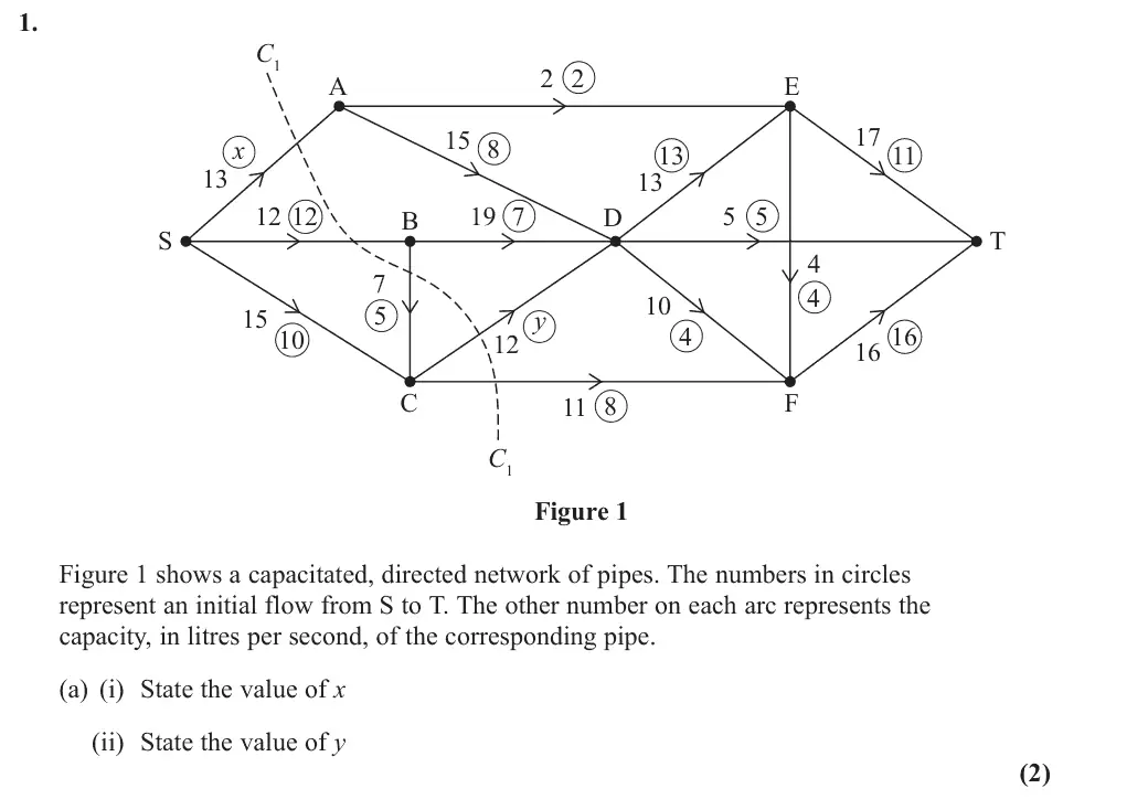
flow in = flow out at A and D: x = 10, y = 7
June 2024 · Paper 4D (Decision 2) · Q1(b)1 mark
Mark scheme (whole question; this part is marked with the orange bar)
Examiner's comment
Most candidates produced a good response to this question and were generally able to answer parts a, b, c and d. Where some candidates had problems was in not drawing the correct cut or
Key points from the mark scheme and examiner's report
initial flow 32
June 2024 · Paper 4D (Decision 2) · Q1(c)1 mark
Mark scheme (whole question; this part is marked with the orange bar)
Examiner's comment
Most candidates produced a good response to this question and were generally able to answer parts a, b, c and d. Where some candidates had problems was in not drawing the correct cut or
Key points from the mark scheme and examiner's report
Mark scheme (whole question; this part is marked with the orange bar)
Examiner's comment
Most candidates produced a good response to this question and were generally able to answer parts a, b, c and d. Where some candidates had problems was in not drawing the correct cut or
Key points from the mark scheme and examiner's report
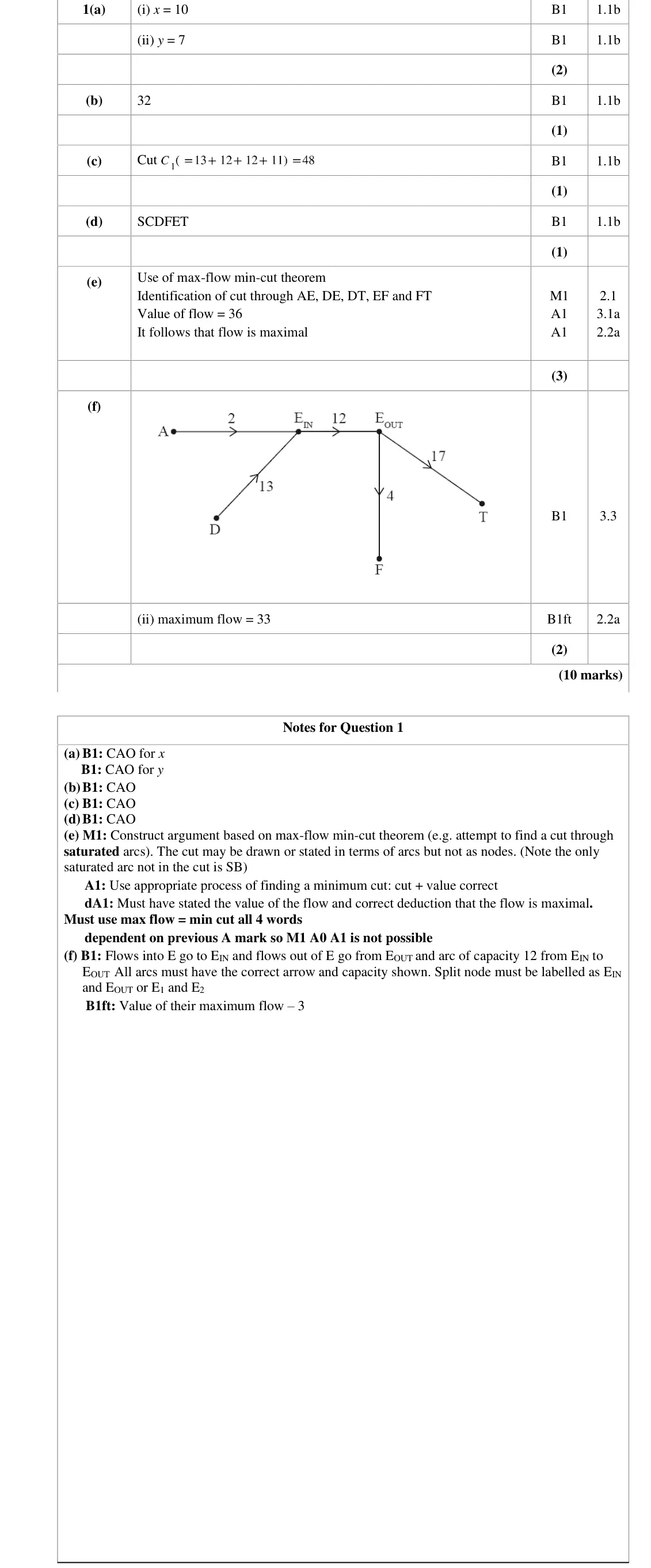
S–C–D–F–E–T, using the backflow in EF
June 2024 · Paper 4D (Decision 2) · Q1(e)3 marks
Mark scheme (whole question; this part is marked with the orange bar)
Examiner's comment
Most candidates produced a good response to this question and were generally able to answer parts a, b, c and d. Where some candidates had problems was in not drawing the correct cut or stating the arcs involved in the cut for (e). Others failed to state the final value of the flow or use the full statement “maximum flow = minimum cut” and so did not score full marks here.
Key points from the mark scheme and examiner's report
max-flow min-cut theorem: cut through AE, DE, DT, EF, FT has capacity 36 = flow 36, so maximal
cut must be drawn or listed as arcs
must state the flow value and 'maximum flow = minimum cut'
June 2024 · Paper 4D (Decision 2) · Q1(f)2 marks
Mark scheme (whole question; this part is marked with the orange bar)
Examiner's comment
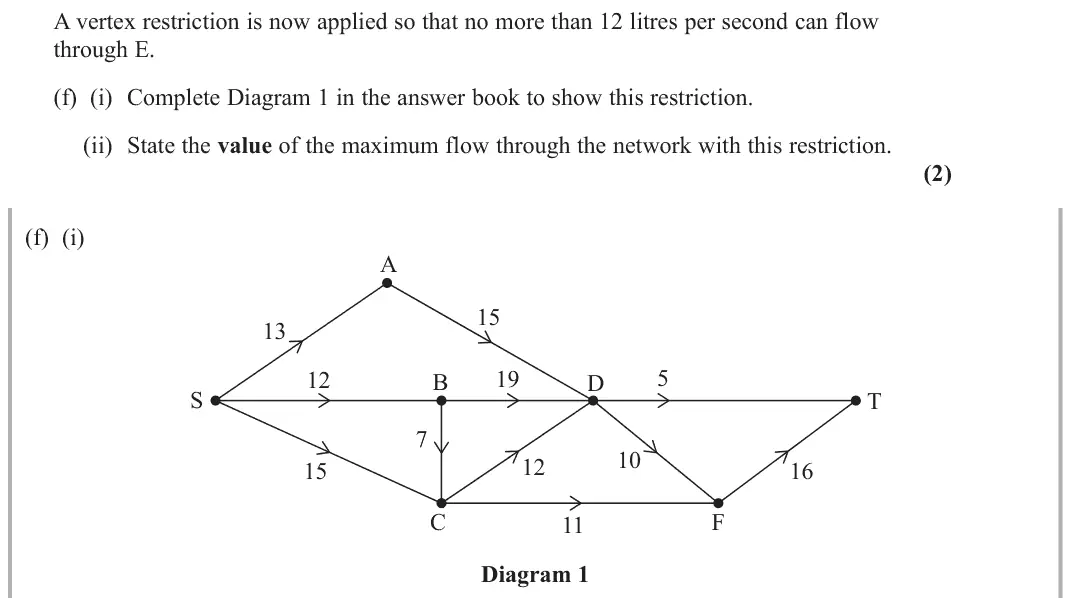
Most candidates produced a good response to this question and were generally able to answer parts a, b, c and d. Where some candidates had problems was in not drawing the correct cut or In (f) a significant number of candidates were unsure how to show the restricted flow using a split node with EIN and EOUT.
Key points from the mark scheme and examiner's report
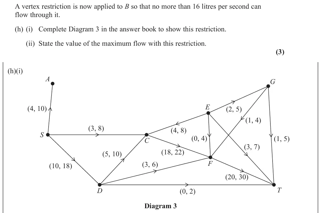
replace E by E_in and E_out joined by an arc of capacity 12
AE and DE into E_in, EF and ET out of E_out
maximum flow becomes 33
many unsure how to split the node
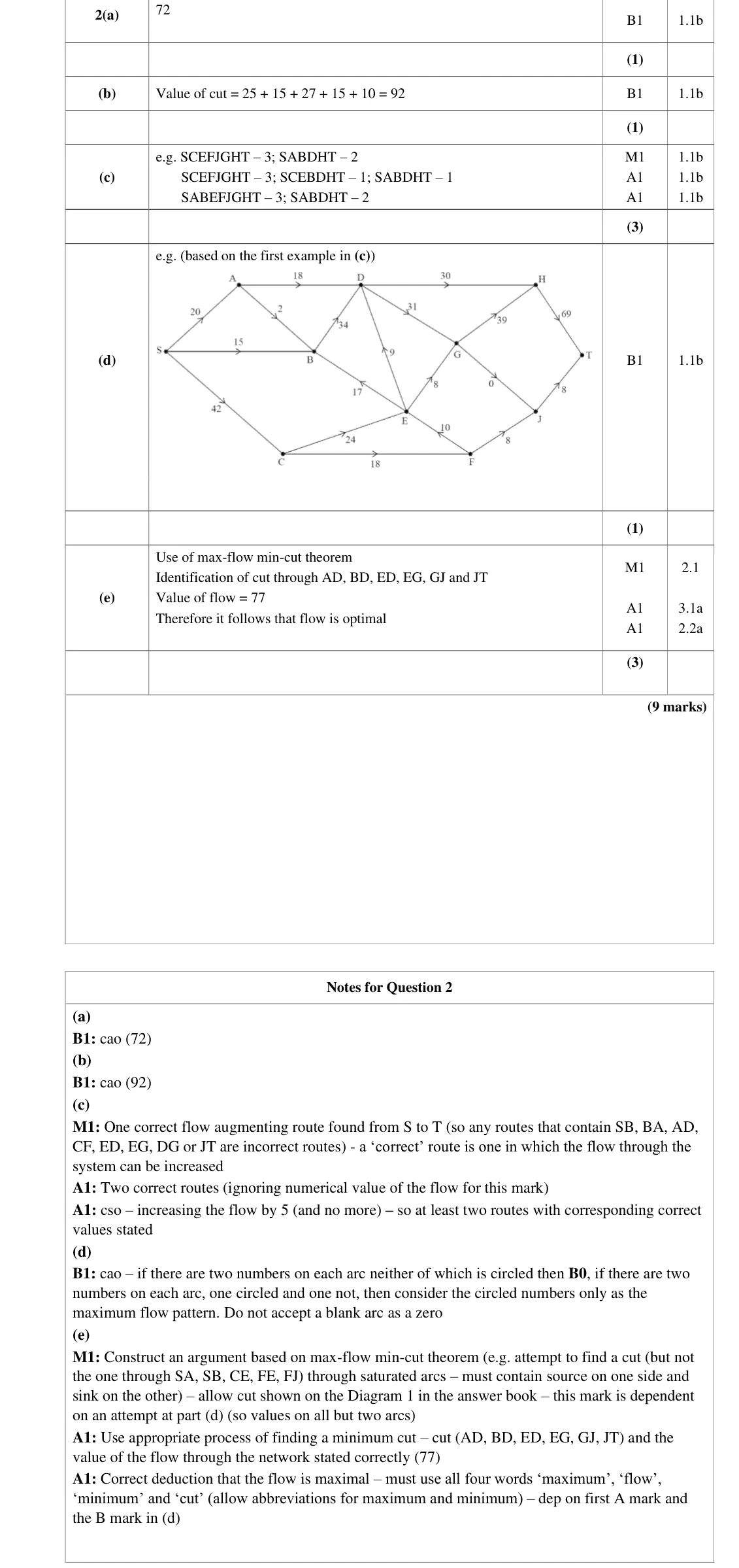
June 2023 · AS Paper 2 (Decision 2) · Q2(a)1 mark
Mark scheme (whole question; this part is marked with the orange bar)
Examiner's comment
In (a) and (b) nearly all candidates correctly stated the initial flow from S to T as 72 and the value of the given cut (as 92).
Key points from the mark scheme and examiner's report
initial flow 72 from the potential backflows into T (or out of S)
June 2023 · AS Paper 2 (Decision 2) · Q2(b)1 mark
Mark scheme (whole question; this part is marked with the orange bar)
Examiner's comment
In (a) and (b) nearly all candidates correctly stated the initial flow from S to T as 72 and the value of the given cut (as 92).
Key points from the mark scheme and examiner's report
25 + 15 + 27 + 15 + 10 = 92 (capacity = excess capacity + backflow on each arc from the source side)
June 2023 · AS Paper 2 (Decision 2) · Q2(c)3 marks
Mark scheme (whole question; this part is marked with the orange bar)
Examiner's comment
Most candidates stated at least one correct flow-augmenting route in part (c) (together with its length) although some gave routes that totalled more than the maximum permissible increase (which was 5). Candidates are reminded that routes should be stated in terms of nodes starting with S and finishing with T.
Key points from the mark scheme and examiner's report
routes as node lists from S to T with flows, e.g. SCEFJGHT 3, SABDHT 2
total increase exactly 5 (some exceeded it)
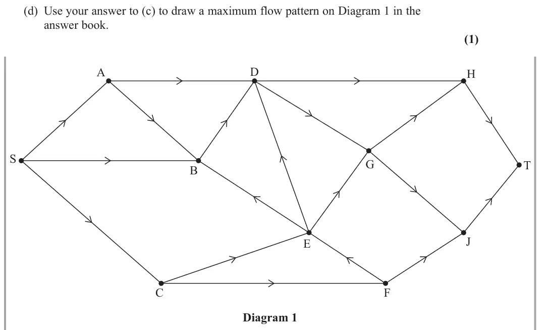
June 2023 · AS Paper 2 (Decision 2) · Q2(d)1 mark
Mark scheme (whole question; this part is marked with the orange bar)
Examiner's comment
Although many candidates correctly found the flow-augmenting routes required (to increase the flow by a maximum of 5 units) it was rare for candidates to draw a correct maximum flow pattern in part (d). Candidates are reminded that no arc should be left blank (a blank is not assumed to be 0) and that each arc should only have a single value written on it (and therefore they should not waste time showing the flow and the capacity on each arc).
Key points from the mark scheme and examiner's report
flow of 77 on Diagram 1
one value on every arc, a blank is not taken as 0
correct patterns were rare
June 2023 · AS Paper 2 (Decision 2) · Q2(e)3 marks
Mark scheme (whole question; this part is marked with the orange bar)
Examiner's comment
Part (e) discriminated well with very few proving that the answer to (d) was optimal. To assist for future series please find below a way in which candidates can set out such a proof: • It is best to state (and not just draw) a cut (that passes through saturated arcs that are directed from the source set to the sink set of nodes together with any arcs with zero flow that are directed from the sink set to source set) - so for this network as a list of arcs this was AD, BD, ED, EG, GJ and JT or as set of nodes S,A,B,C,E,F,J , D,G,H,T . • State the capacity of this cut and hence what this implies about the minimum cut e.g., the value of this cut is 77 which implies that the minimum cut ⩽77 • State the value of the flow through the network after augmentation and what this implied about the maximum flow e.g., the current flow through the network is 77 which implies that the maximum flow is ⩾77 • Conclude the proof by referring to the maximum flow-minimum cut theorem e.g. the min. cut is ⩽77 and the max. flow is ⩾77 but by the maximum flow-minimum cut theorem the max. flow is equal to min. cut therefore the maximum flow is 77 and therefore the flow is indeed optimal.
Key points from the mark scheme and examiner's report
cut through AD, BD, ED, EG, GJ, JT has value 77 = flow
use the words maximum flow = minimum cut
the cut from (b) does not work
few complete proofs
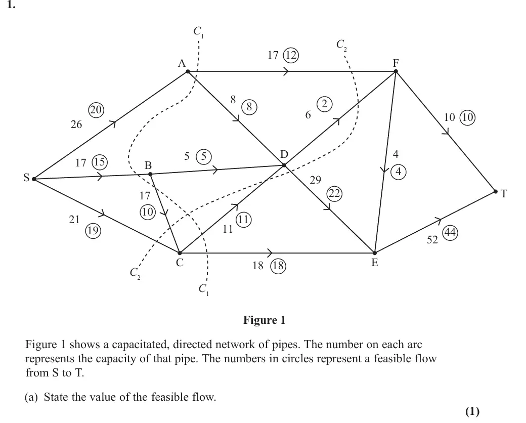
June 2023 · Paper 4D (Decision 2) · Q1(a)1 mark
Mark scheme (whole question; this part is marked with the orange bar)
Examiner's comment
This question proved to be accessible for most candidates. Most candidates stated the value of the initial flow correctly. Some made errors calculating the value of the cuts, either by omitting an arc or by including arcs flowing from the sink to the source. Most candidates found the correct flow augmenting route. A significant number of candidates made errors attempting to prove that the flow is maximal. Most either drew or stated a cut, although some incorrectly including AF in their cut. The most common error was failing to state the value of either the flow or the cut (or both) and some candidates failed to make reference to the Maximum Flow – Minimum Cut Theorem.
Key points from the mark scheme and examiner's report
value of the feasible flow 54
June 2023 · Paper 4D (Decision 2) · Q1(b)2 marks
Mark scheme (whole question; this part is marked with the orange bar)
Examiner's comment
This question proved to be accessible for most candidates. Most candidates stated the value of the initial flow correctly. Some made errors calculating the value of the cuts, either by omitting an arc or by including arcs flowing from the sink to the source. Most candidates found the correct flow augmenting route. A significant number of candidates made errors attempting to prove that the flow is maximal. Most either drew or stated a cut, although some incorrectly including AF in their cut. The most common error was failing to state the value of either the flow or the cut (or both) and some candidates failed to make reference to the Maximum Flow – Minimum Cut Theorem.
Key points from the mark scheme and examiner's report
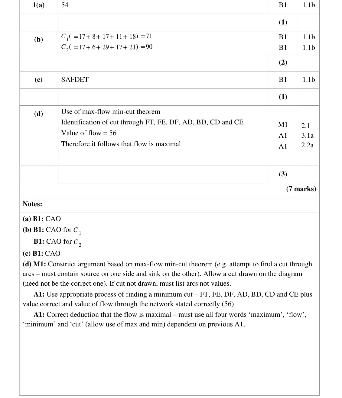
C1 = 17 + 8 + 17 + 11 + 18 = 71
C2 = 17 + 6 + 29 + 17 + 21 = 90
arcs from sink side to source side count 0
omitting an arc was a common error
June 2023 · Paper 4D (Decision 2) · Q1(c)1 mark
Mark scheme (whole question; this part is marked with the orange bar)
Examiner's comment
This question proved to be accessible for most candidates. Most candidates stated the value of the initial flow correctly. Some made errors calculating the value of the cuts, either by omitting an arc or by including arcs flowing from the sink to the source. Most candidates found the correct flow augmenting route. A significant number of candidates made errors attempting to prove that the flow is maximal. Most either drew or stated a cut, although some incorrectly including AF in their cut. The most common error was failing to state the value of either the flow or the cut (or both) and some candidates failed to make reference to the Maximum Flow – Minimum Cut Theorem.
Key points from the mark scheme and examiner's report
S–A–F–D–E–T (uses backflow in DF)
June 2023 · Paper 4D (Decision 2) · Q1(d)3 marks
Mark scheme (whole question; this part is marked with the orange bar)
Examiner's comment
This question proved to be accessible for most candidates. Most candidates stated the value of the initial flow correctly. Some made errors calculating the value of the cuts, either by omitting an arc or by including arcs flowing from the sink to the source. Most candidates found the correct flow augmenting route. A significant number of candidates made errors attempting to prove that the flow is maximal. Most either drew or stated a cut, although some incorrectly including AF in their cut. The most common error was failing to state the value of either the flow or the cut (or both) and some candidates failed to make reference to the Maximum Flow – Minimum Cut Theorem.
Key points from the mark scheme and examiner's report
max-flow min-cut theorem: cut through FT, FE, DF, AD, BD, CD, CE has capacity 56 = flow 56, so maximal
must state both values and use the words maximum, flow, minimum, cut
AF wrongly included in some cuts
June 2022 · AS Paper 2 (Decision 2) · Q2(a)1 mark
Mark scheme (whole question; this part is marked with the orange bar)
Examiner's comment
In (a) and (b) nearly all candidates correctly stated the feasible flow from S to T as 50 and the eight saturated arcs respectively.
Key points from the mark scheme and examiner's report
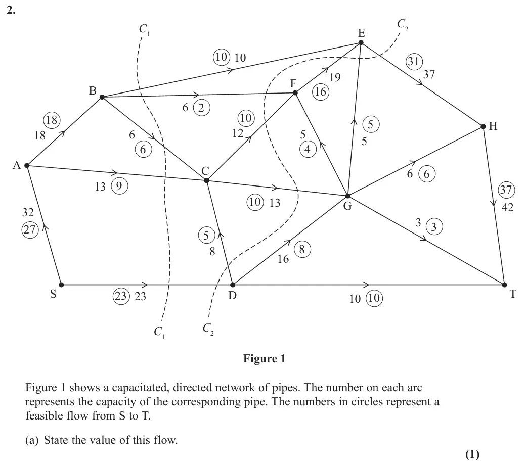
value of the flow is 50
June 2022 · AS Paper 2 (Decision 2) · Q2(b)1 mark
Mark scheme (whole question; this part is marked with the orange bar)
Examiner's comment
In (a) and (b) nearly all candidates correctly stated the feasible flow from S to T as 50 and the eight saturated arcs respectively.
Key points from the mark scheme and examiner's report
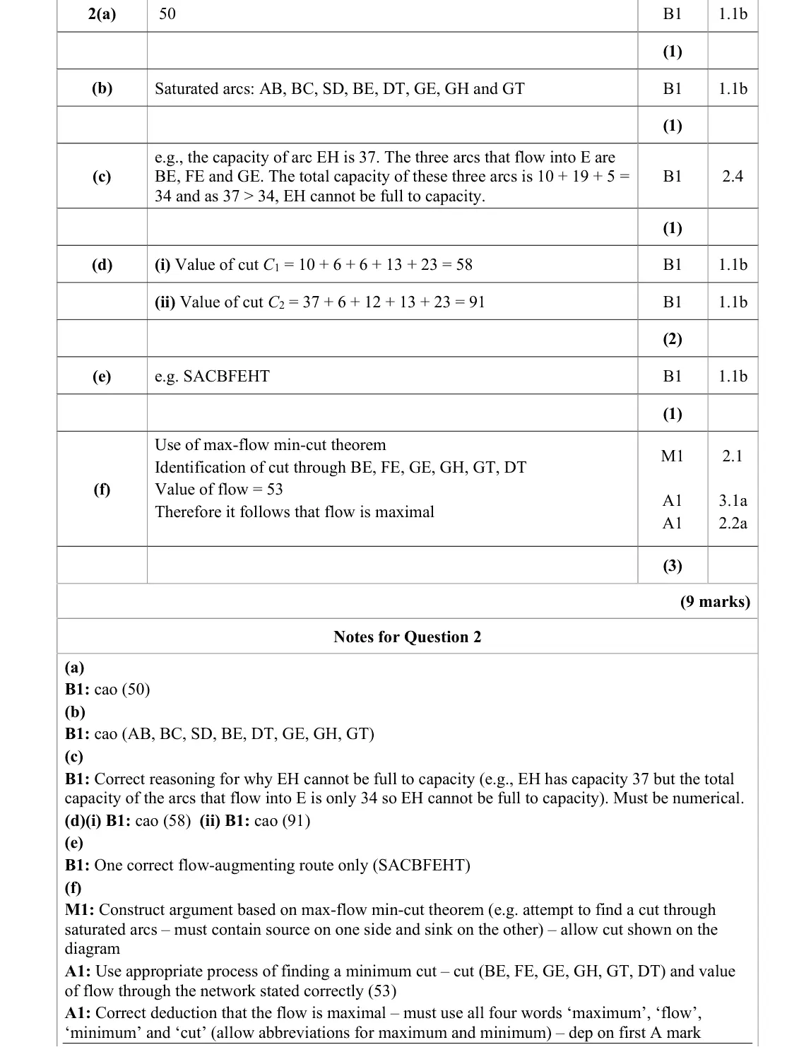
AB, BC, SD, BE, DT, GE, GH, GT
June 2022 · AS Paper 2 (Decision 2) · Q2(c)1 mark
Mark scheme (whole question; this part is marked with the orange bar)
Examiner's comment
In (c) several candidates struggled to explain why arc EC could never by full to capacity. Not all candidates explained that the total capacity of the three arcs (BE, FE and GE) leading into E was 34 but the maximum flow of the one arc (EH) out of E was 37.
Key points from the mark scheme and examiner's report
EH has capacity 37 but the arcs into E (BE, FE, GE) total only 10 + 19 + 5 = 34
must be numerical
June 2022 · AS Paper 2 (Decision 2) · Q2(d)2 marks
Mark scheme (whole question; this part is marked with the orange bar)
Examiner's comment
In (d) the most common error in calculating the value of the second cut was to include values for arcs FE, DC and/or GE even though these arcs were directed from the sink set of nodes to the source set of nodes for this cut.
Key points from the mark scheme and examiner's report
commonest error was adding FE, DC or GE, which run from the sink side to the source side
June 2022 · AS Paper 2 (Decision 2) · Q2(e)1 mark
Mark scheme (whole question; this part is marked with the orange bar)
Examiner's comment
Most candidates correctly stated the required flow-augmenting route in (e) although some gave more than one route (even though the question specifically asked for a single route).
Key points from the mark scheme and examiner's report
single route SACBFEHT using the backflow on BC
some gave more than one route
June 2022 · AS Paper 2 (Decision 2) · Q2(f)3 marks
Mark scheme (whole question; this part is marked with the orange bar)
Examiner's comment
Part (f) discriminated well with very few proving that the flow was optimal. To assist for future series please find below a way in which candidates can set out such a proof: • It is best to state (and not just draw) a cut (that passes through saturated arcs that are directed from the source set to the sink set of nodes together with any arcs with zero flow that are directed from the sink set to source set) - so for this network as a list of arcs this was BE, FE, GE, GH, GT and DT or as set of nodes { } { } S,A,B,C,D,F,G , E,H,T . • State the capacity of this cut and hence what this implies about the minimum cut e.g. the value of this cut is 53 which implies that the minimum cut 53 • State the value of the flow through the network after augmentation and what this implied about the maximum flow e.g. the current flow through the network is 53 which implies that the maximum flow is 53 • Conclude the proof by referring to the maximum flow-minimum cut theorem e.g. the min. cut is 53 and the max. flow is 53 but by the maximum flow-minimum cut theorem the max. flow is equal to min. cut therefore the maximum flow is 53 and therefore the flow is indeed optimal.
Key points from the mark scheme and examiner's report
cut through BE, FE, GE, GH, GT, DT has value 53 = new flow
must use the words maximum flow = minimum cut
very few complete proofs
June 2022 · Paper 4D (Decision 2) · Q4(a)1 mark
Mark scheme (whole question; this part is marked with the orange bar)
Examiner's comment
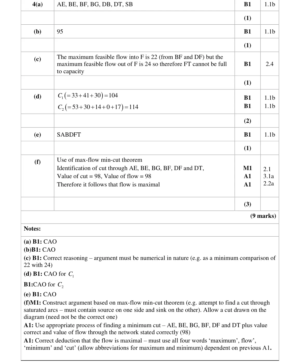
Most candidates correctly listed all 7 saturated arcs, although a few failed to do so, only giving 6 of them. Almost all candidates then stated the correct initial flow of 95 and many gave a correct explanation that the maximum flow into F was 22 which is less than 24 the capacity of FT. Some did not give both figures and were penalised here. Most candidates found the correct value of the cut C1but a significant number made an error with C2 stating 108 having incorrectly subtracted the capacity of BD. A significant number of candidates failed to find the correct flow augmenting route of SABDFT and other errors here included a descriptive approach, listing the route as a series of arcs with associated actions, or trying to give multiple routes. While many candidates had some idea of the max-flow-min-cut theorem, it was often not used correctly. Some failed to state the value of the flow. Others did not draw or list the arcs in the cut correctly or did not state the value of the cut. Some then failed to use correct wording and make the deduction that the flow was maximal. A surprising number of candidates called their augmented flow of 98 ‘initial flow’, which, though incorrect, was not penalised.
Key points from the mark scheme and examiner's report
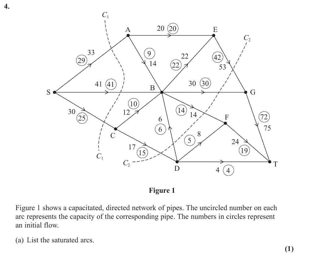
AE, BE, BF, BG, DB, DT, SB (7 arcs
some gave only 6)
June 2022 · Paper 4D (Decision 2) · Q4(b)1 mark
Mark scheme (whole question; this part is marked with the orange bar)
Examiner's comment
Most candidates correctly listed all 7 saturated arcs, although a few failed to do so, only giving 6 of them. Almost all candidates then stated the correct initial flow of 95 and many gave a correct explanation that the maximum flow into F was 22 which is less than 24 the capacity of FT. Some did not give both figures and were penalised here. Most candidates found the correct value of the cut C1but a significant number made an error with C2 stating 108 having incorrectly subtracted the capacity of BD. A significant number of candidates failed to find the correct flow augmenting route of SABDFT and other errors here included a descriptive approach, listing the route as a series of arcs with associated actions, or trying to give multiple routes. While many candidates had some idea of the max-flow-min-cut theorem, it was often not used correctly. Some failed to state the value of the flow. Others did not draw or list the arcs in the cut correctly or did not state the value of the cut. Some then failed to use correct wording and make the deduction that the flow was maximal. A surprising number of candidates called their augmented flow of 98 ‘initial flow’, which, though incorrect, was not penalised.
Key points from the mark scheme and examiner's report
initial flow 95
June 2022 · Paper 4D (Decision 2) · Q4(c)1 mark
Mark scheme (whole question; this part is marked with the orange bar)
Examiner's comment
Most candidates correctly listed all 7 saturated arcs, although a few failed to do so, only giving 6 of them. Almost all candidates then stated the correct initial flow of 95 and many gave a correct explanation that the maximum flow into F was 22 which is less than 24 the capacity of FT. Some did not give both figures and were penalised here. Most candidates found the correct value of the cut C1but a significant number made an error with C2 stating 108 having incorrectly subtracted the capacity of BD. A significant number of candidates failed to find the correct flow augmenting route of SABDFT and other errors here included a descriptive approach, listing the route as a series of arcs with associated actions, or trying to give multiple routes. While many candidates had some idea of the max-flow-min-cut theorem, it was often not used correctly. Some failed to state the value of the flow. Others did not draw or list the arcs in the cut correctly or did not state the value of the cut. Some then failed to use correct wording and make the deduction that the flow was maximal. A surprising number of candidates called their augmented flow of 98 ‘initial flow’, which, though incorrect, was not penalised.
Key points from the mark scheme and examiner's report
maximum flow into F is 14 + 8 = 22 (BF and DF) but FT has capacity 24
must compare the two figures
June 2022 · Paper 4D (Decision 2) · Q4(d)2 marks
Mark scheme (whole question; this part is marked with the orange bar)
Examiner's comment
Most candidates correctly listed all 7 saturated arcs, although a few failed to do so, only giving 6 of them. Almost all candidates then stated the correct initial flow of 95 and many gave a correct explanation that the maximum flow into F was 22 which is less than 24 the capacity of FT. Some did not give both figures and were penalised here. Most candidates found the correct value of the cut C1but a significant number made an error with C2 stating 108 having incorrectly subtracted the capacity of BD. A significant number of candidates failed to find the correct flow augmenting route of SABDFT and other errors here included a descriptive approach, listing the route as a series of arcs with associated actions, or trying to give multiple routes. While many candidates had some idea of the max-flow-min-cut theorem, it was often not used correctly. Some failed to state the value of the flow. Others did not draw or list the arcs in the cut correctly or did not state the value of the cut. Some then failed to use correct wording and make the deduction that the flow was maximal. A surprising number of candidates called their augmented flow of 98 ‘initial flow’, which, though incorrect, was not penalised.
Key points from the mark scheme and examiner's report
C1 = 33 + 41 + 30 = 104
C2 = 53 + 30 + 14 + 0 + 17 = 114 (backward arc BD counts 0, not subtracted: 108 was a common error)
June 2022 · Paper 4D (Decision 2) · Q4(e)1 mark
Mark scheme (whole question; this part is marked with the orange bar)
Examiner's comment
Most candidates correctly listed all 7 saturated arcs, although a few failed to do so, only giving 6 of them. Almost all candidates then stated the correct initial flow of 95 and many gave a correct explanation that the maximum flow into F was 22 which is less than 24 the capacity of FT. Some did not give both figures and were penalised here. Most candidates found the correct value of the cut C1but a significant number made an error with C2 stating 108 having incorrectly subtracted the capacity of BD. A significant number of candidates failed to find the correct flow augmenting route of SABDFT and other errors here included a descriptive approach, listing the route as a series of arcs with associated actions, or trying to give multiple routes. While many candidates had some idea of the max-flow-min-cut theorem, it was often not used correctly. Some failed to state the value of the flow. Others did not draw or list the arcs in the cut correctly or did not state the value of the cut. Some then failed to use correct wording and make the deduction that the flow was maximal. A surprising number of candidates called their augmented flow of 98 ‘initial flow’, which, though incorrect, was not penalised.
Key points from the mark scheme and examiner's report
S–A–B–D–F–T, reducing the flow in DB (backflow)
a list of arcs with actions or multiple routes not accepted
June 2022 · Paper 4D (Decision 2) · Q4(f)3 marks
Mark scheme (whole question; this part is marked with the orange bar)
Examiner's comment
Most candidates correctly listed all 7 saturated arcs, although a few failed to do so, only giving 6 of them. Almost all candidates then stated the correct initial flow of 95 and many gave a correct explanation that the maximum flow into F was 22 which is less than 24 the capacity of FT. Some did not give both figures and were penalised here. Most candidates found the correct value of the cut C1but a significant number made an error with C2 stating 108 having incorrectly subtracted the capacity of BD. A significant number of candidates failed to find the correct flow augmenting route of SABDFT and other errors here included a descriptive approach, listing the route as a series of arcs with associated actions, or trying to give multiple routes. While many candidates had some idea of the max-flow-min-cut theorem, it was often not used correctly. Some failed to state the value of the flow. Others did not draw or list the arcs in the cut correctly or did not state the value of the cut. Some then failed to use correct wording and make the deduction that the flow was maximal. A surprising number of candidates called their augmented flow of 98 ‘initial flow’, which, though incorrect, was not penalised.
Key points from the mark scheme and examiner's report
max-flow min-cut theorem: cut through AE, BE, BG, BF, DF, DT has capacity 98 = flow 98, so maximal
must use the words maximum, flow, minimum, cut
often the flow value or cut value not stated
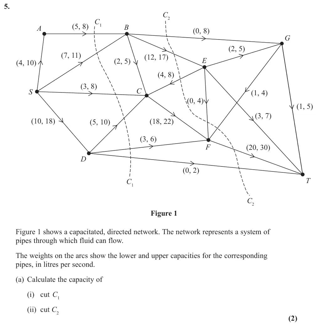
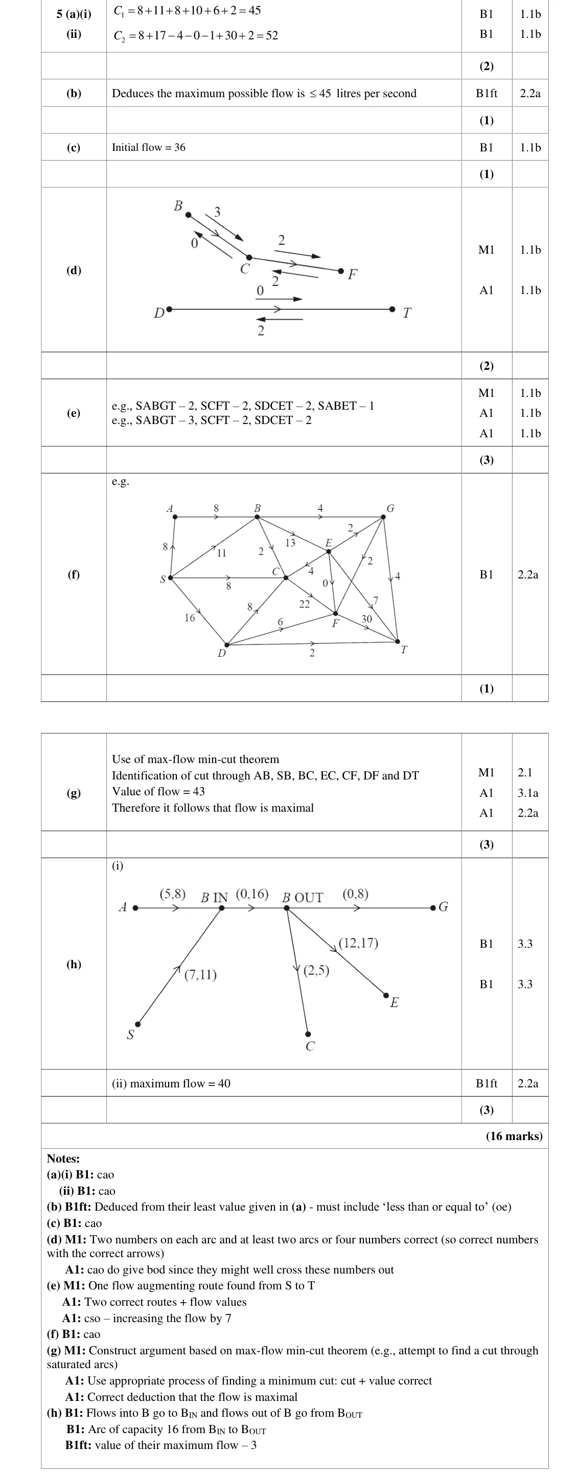
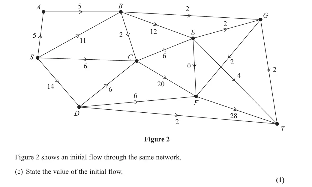
Nov 2021 · Paper 4D (Decision 2) · Q5(a)2 marks
Mark scheme (whole question; this part is marked with the orange bar)
Key points from the mark scheme and examiner's report
arcs directed from the sink side back to the source side count zero
Oct 2020 · AS Paper 2 (Decision 2) · Q1(d)1 mark
Mark scheme (whole question; this part is marked with the orange bar)
Key points from the mark scheme and examiner's report
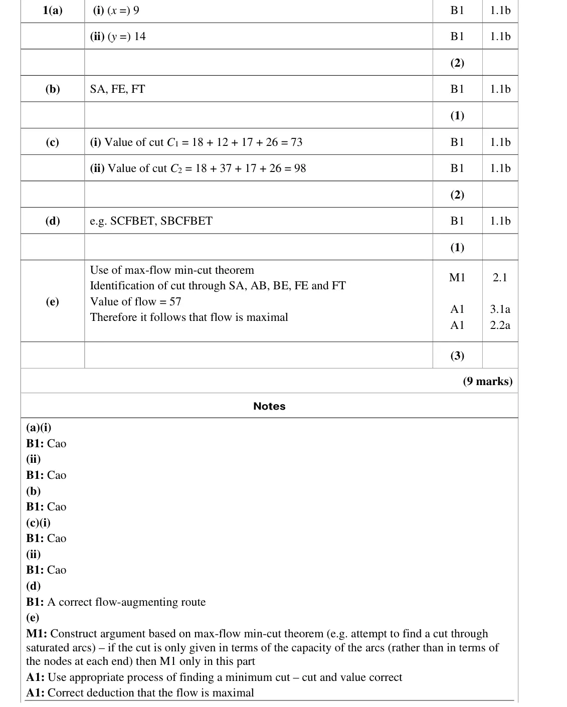
a route using CF with spare capacity 2 along every forward arc and backflow on BF, e.g. SCFBET
Oct 2020 · AS Paper 2 (Decision 2) · Q1(e)3 marks
Mark scheme (whole question; this part is marked with the orange bar)
Key points from the mark scheme and examiner's report
cut through SA, AB, BE, FE, FT has value 57 = new flow
cut must be given by its arcs or nodes, not just capacities
state maximum flow = minimum cut
Oct 2020 · Paper 4D (Decision 2) · Q5(a)1 mark
Mark scheme (whole question; this part is marked with the orange bar)
Key points from the mark scheme and examiner's report
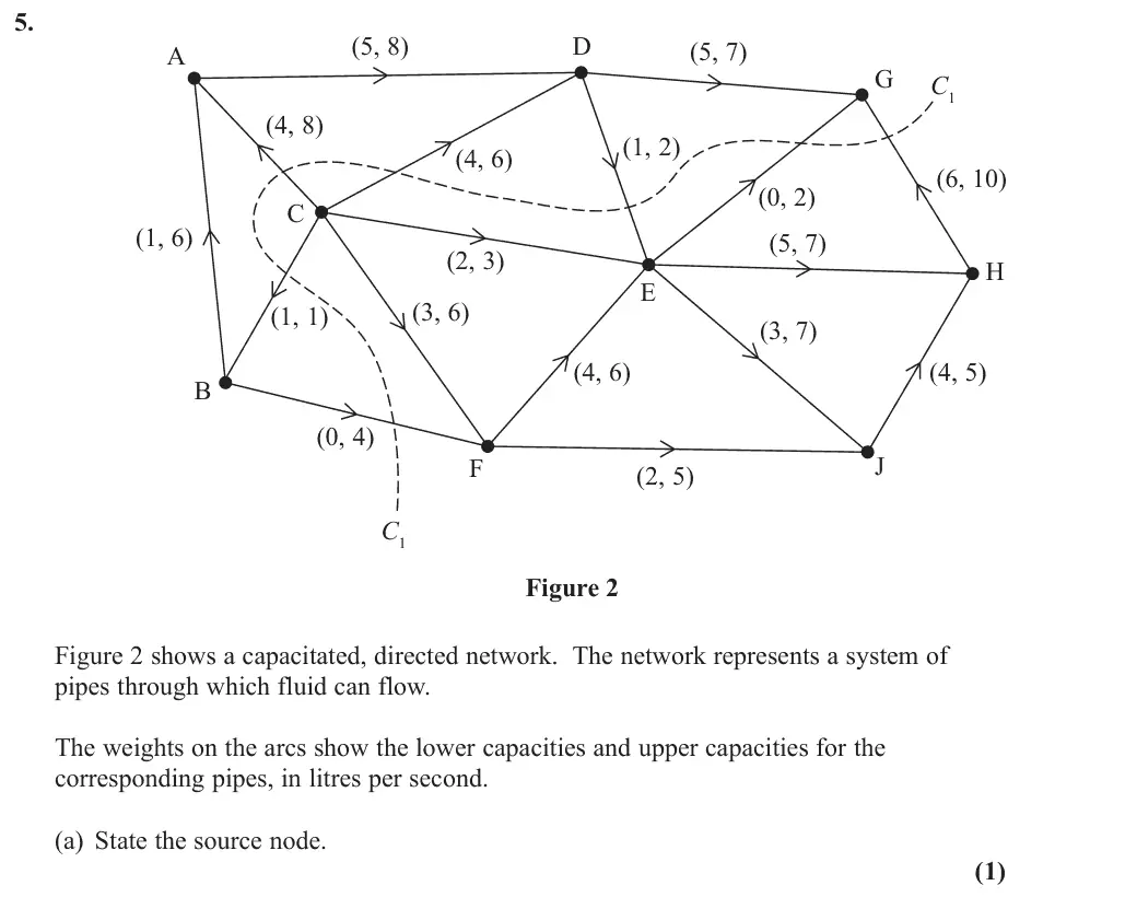
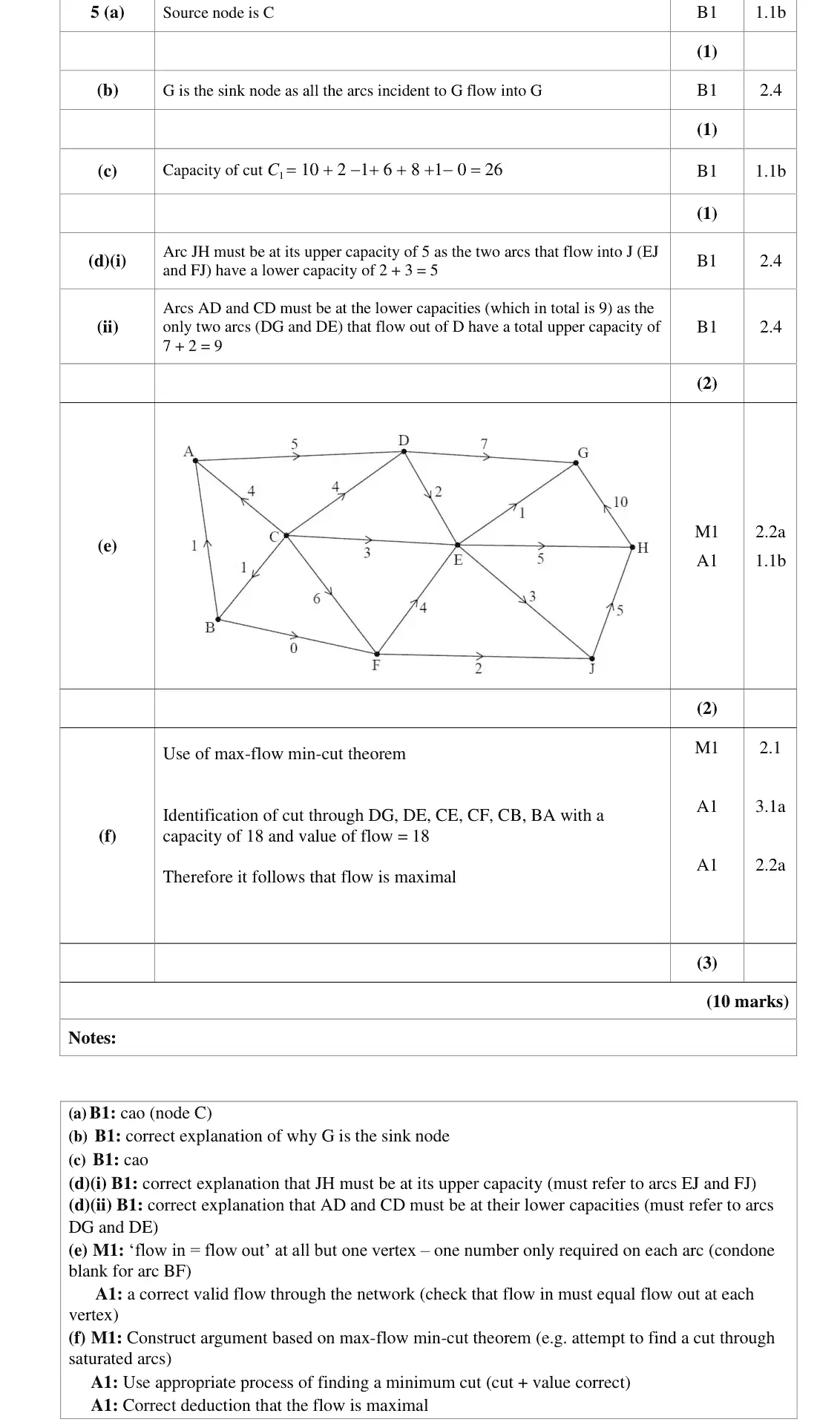
source is C (all arcs at C point away)
Oct 2020 · Paper 4D (Decision 2) · Q5(b)1 mark
Mark scheme (whole question; this part is marked with the orange bar)
Key points from the mark scheme and examiner's report
every arc incident to G flows into G
Oct 2020 · Paper 4D (Decision 2) · Q5(c)1 mark
Mark scheme (whole question; this part is marked with the orange bar)
Key points from the mark scheme and examiner's report
add upper capacities of arcs crossing from source side to sink side, subtract lower capacities of arcs crossing back: 10 + 2 − 1 + 6 + 8 + 1 − 0 = 26
Oct 2020 · Paper 4D (Decision 2) · Q5(d)2 marks
Mark scheme (whole question; this part is marked with the orange bar)
Key points from the mark scheme and examiner's report
(i) lower capacities into J (EJ, FJ) total 2 + 3 = 5 = upper capacity of JH
(ii) upper capacities out of D (DG, DE) total 7 + 2 = 9 = lower capacities of AD + CD
must name these arcs
Oct 2020 · Paper 4D (Decision 2) · Q5(e)2 marks
Mark scheme (whole question; this part is marked with the orange bar)
Key points from the mark scheme and examiner's report
one number per arc, flow in = flow out at every vertex, all flows within the (lower, upper) bounds
Oct 2020 · Paper 4D (Decision 2) · Q5(f)3 marks
Mark scheme (whole question; this part is marked with the orange bar)
Key points from the mark scheme and examiner's report
max-flow min-cut theorem: cut through DG, DE, CE, CF, CB, BA has capacity 18 = flow, so maximal
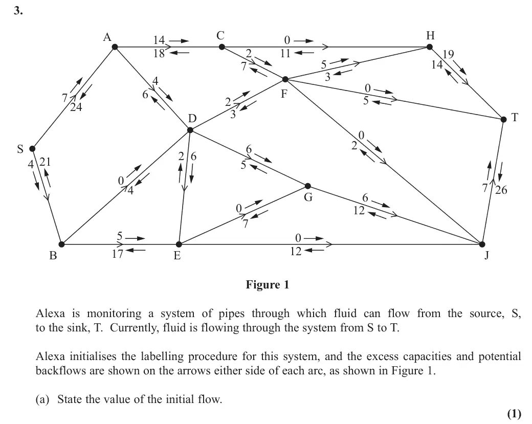
June 2019 · AS Paper 2 (Decision 2) · Q3(a)1 mark
Mark scheme (whole question; this part is marked with the orange bar)
Examiner's comment
In part (a) nearly all candidates correctly stated the initial flow as 45.
Key points from the mark scheme and examiner's report
initial flow 45 (sum of potential backflows on arcs into T, or out of S)
June 2019 · AS Paper 2 (Decision 2) · Q3(b)1 mark
Mark scheme (whole question; this part is marked with the orange bar)
Examiner's comment
In part (b) many candidates struggled to explain why arcs DF and DG can never both by full to capacity. Very few explained that the total capacity of these two arcs is 16 but the maximum flow of the two arcs that flow into D (AD and BD) is only 14. Many incorrectly based their argument on the flow out of D without realising that flow could leave D via arc DE.
Key points from the mark scheme and examiner's report
capacity of DF + DG = 5 + 11 = 16 but at most 10 + 4 = 14 can flow into D (AD and BD)
many wrongly argued from the flow out of D, forgetting DE
June 2019 · AS Paper 2 (Decision 2) · Q3(c)1 mark
Mark scheme (whole question; this part is marked with the orange bar)
Examiner's comment
In part (c) the most common error in calculating the value of the given cut was to include a value for arc DE even though this arc was directed from the sink set of nodes to the source set of nodes for this cut.
Key points from the mark scheme and examiner's report
32 + 10 + 4 + 7 + 12 = 65
commonest error was adding DE, which is directed from the sink set to the source set
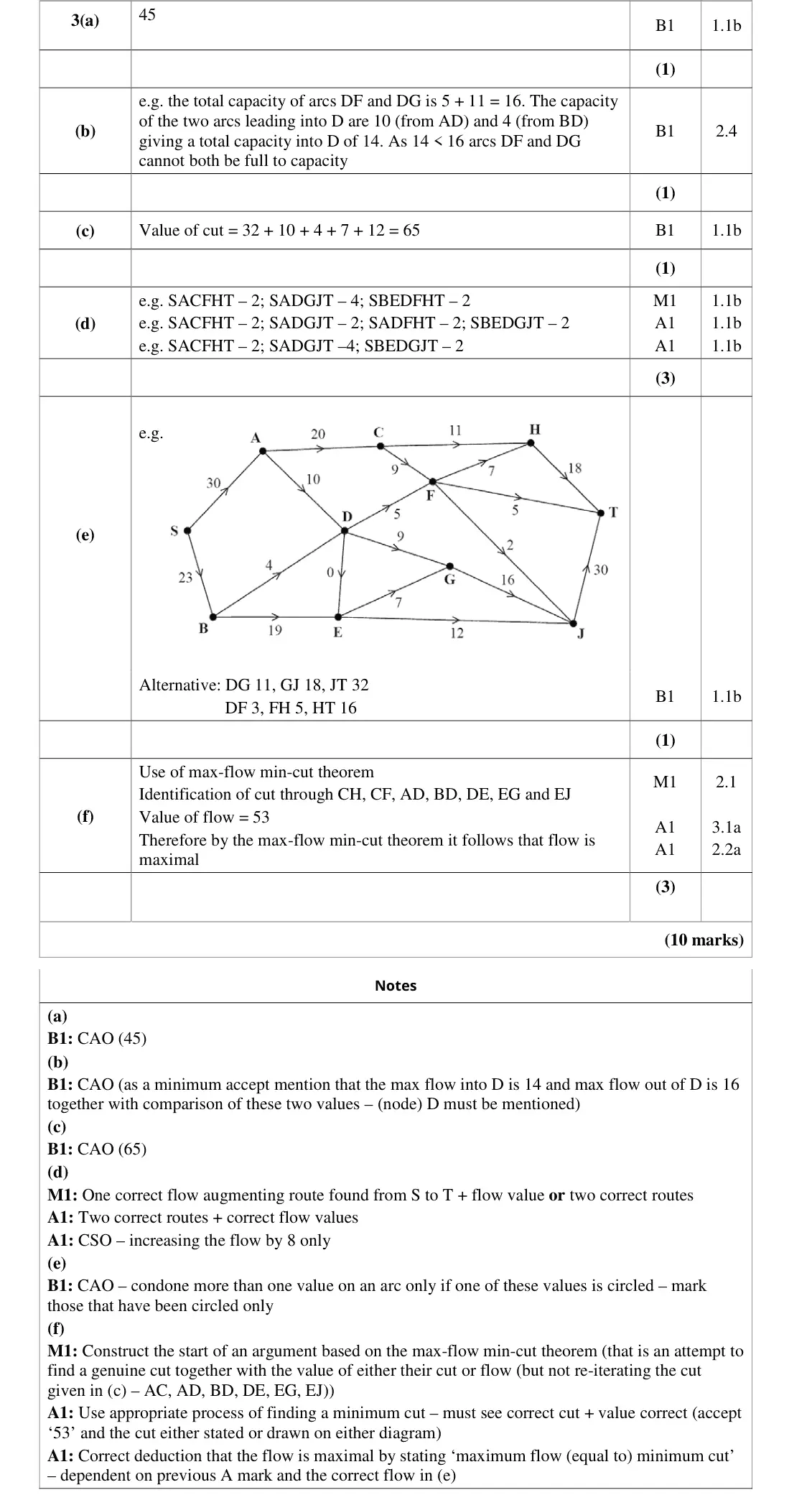
June 2019 · AS Paper 2 (Decision 2) · Q3(d)3 marks
Mark scheme (whole question; this part is marked with the orange bar)
Examiner's comment
Most candidates could correctly apply the labelling procedure in part (d) to find at least two correct flow-augmenting routes (and corresponding flows) but not all managed to increase the flow by the correct amount of 8 (and some surprisingly managed to increase the flow to 10).
Key points from the mark scheme and examiner's report
list routes with flows, e.g. SACFHT 2, SADGJT 4, SBEDGJT 2
the flow increases by exactly 8 to 53
some augmented by 10
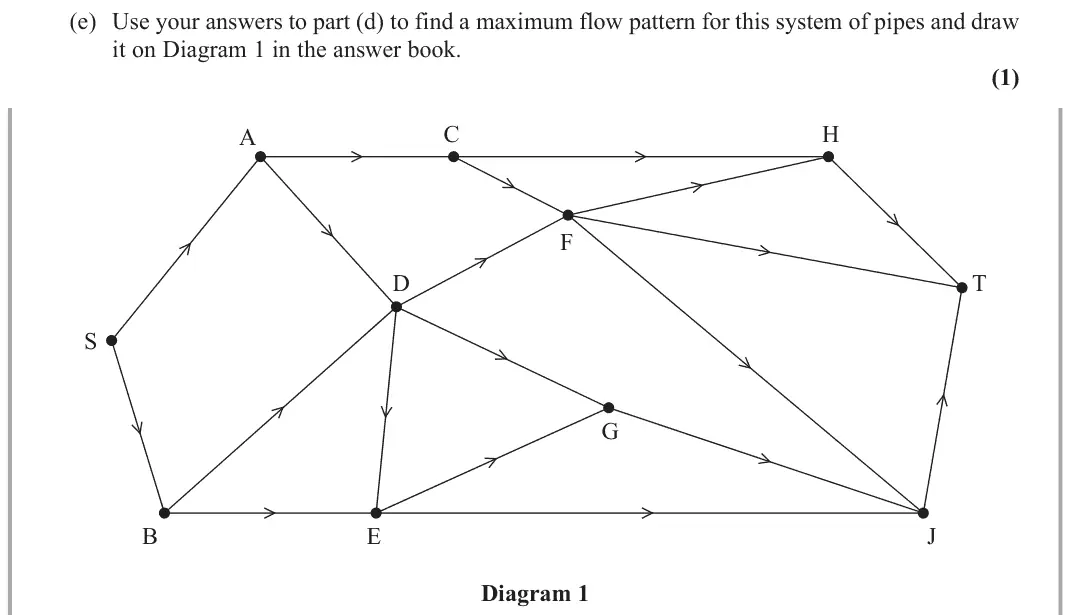
June 2019 · AS Paper 2 (Decision 2) · Q3(e)1 mark
Mark scheme (whole question; this part is marked with the orange bar)
Examiner's comment
In part (e) candidates are reminded of the following two points when showing a flow on a diagram. There should only be one number on each arc and all arcs should be assigned a value (even if this value is zero). Both points were condoned by examiners this series, but this may not be so in the future. State the value of the flow through the network after augmentation and what this implied about the maximum flow e.g. the current flow through the network is 53 which implies that the maximum flow is 53 Conclude the proof by referring to the maximum flow-minimum cut theorem e.g. the min. cut is 53 and the max. flow is 53 but by the maximum flow-minimum cut theorem the max. flow is equal to min. cut therefore the maximum flow is 53 and therefore the flow in part (e) is indeed optimal.
Key points from the mark scheme and examiner's report
flow of 53 on Diagram 1
one number on every arc, including zeros
June 2019 · AS Paper 2 (Decision 2) · Q3(f)3 marks
Mark scheme (whole question; this part is marked with the orange bar)
Examiner's comment
Part (f) discriminated well with very few proving that the flow in part (e) was optimal. To assist for future series please find below a way in which candidates can set out such a proof: It is best to state (and not just draw) a cut (that passes through saturated arcs that are directed from the source set to the sink set of nodes together with any arcs with zero flow that are directed from the sink set to source set) - so for this network as a list of arcs this was CH, CF, AD, BD, DE, EG and EJ or as set of nodes S,A,B,C,E , D,F,G,H,J,T . State the capacity of this cut and hence what this implies about the minimum cut e.g. the value of this cut is 53 which implies that the minimum cut 53
Key points from the mark scheme and examiner's report
cut through CH, CF, AD, BD, DE, EG, EJ has value 53 = flow
state maximum flow = minimum cut
the cut from (c) cannot be reused
few gave a full proof
June 2019 · Paper 4D (Decision 2) · Q6(a)2 marks
Mark scheme (whole question; this part is marked with the orange bar)
Examiner's comment
This question produced a mixture of responses. With a heavy problem solving and reasoning emphasis, it was found to be challenging by many candidates despite being a familiar area of the specification. Part (a) and (b) are very standard questions and as such were the most successful for candidates.
Key points from the mark scheme and examiner's report
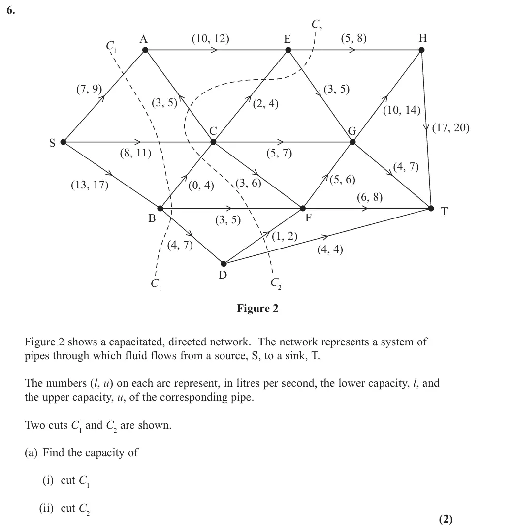
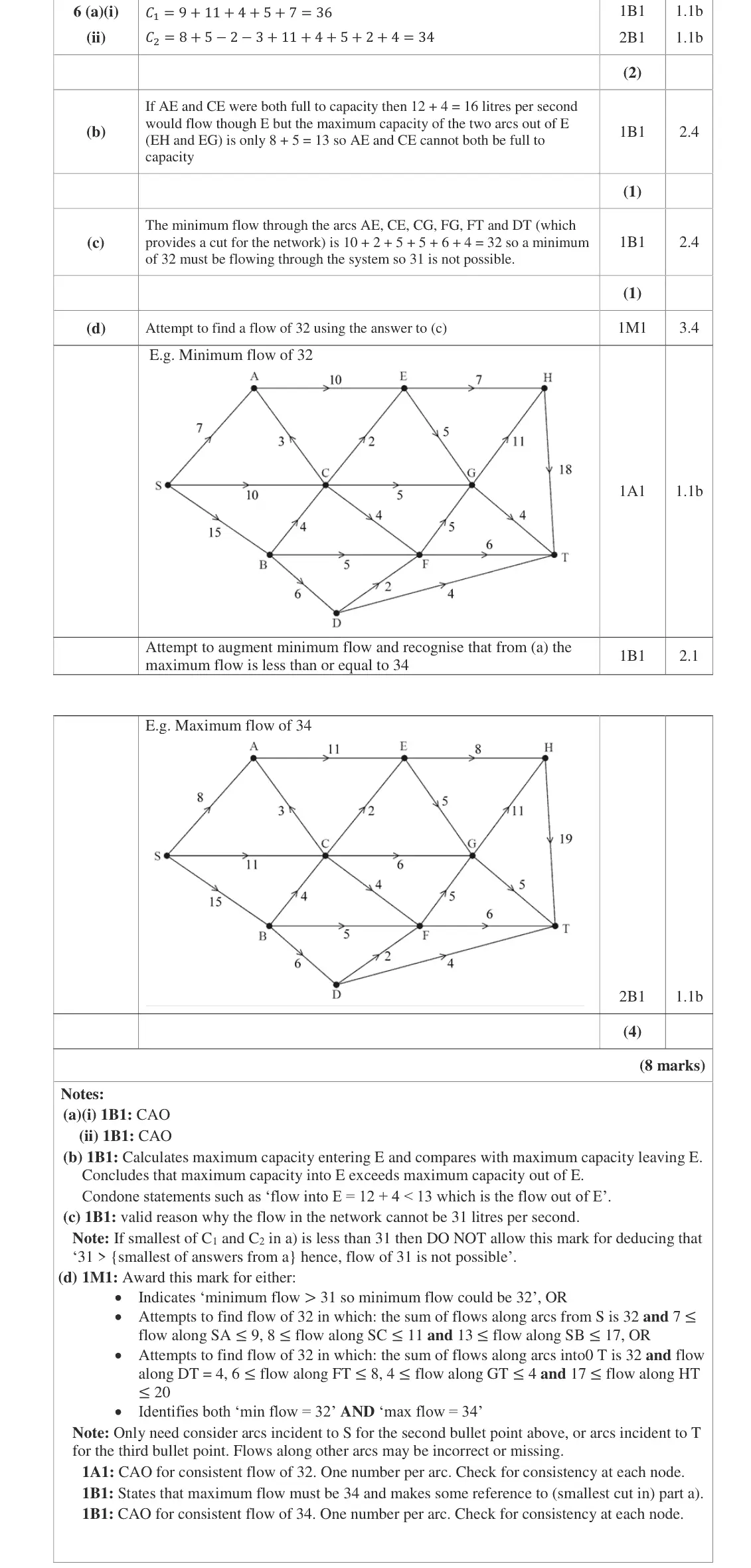
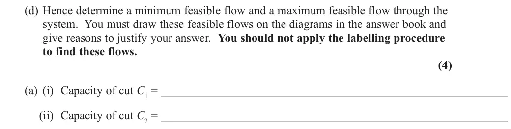
cut capacity = sum of upper capacities forward minus lower capacities of backward arcs: C1 = 36, C2 = 34
errors in (ii) were common
June 2019 · Paper 4D (Decision 2) · Q6(b)1 mark
Mark scheme (whole question; this part is marked with the orange bar)
Examiner's comment
This question produced a mixture of responses. With a heavy problem solving and reasoning emphasis, it was found to be challenging by many candidates despite being a familiar area of the specification. Part (a) and (b) are very standard questions and as such were the most successful for candidates. Nonetheless, the number of incorrect answers in (a) – particularly (a)(ii) was worrying at this level. Part (b) was almost always correct although some responses which focussed on only the maximum flow into E or the maximum flow out of E rather than comparing the two values were insufficient for the mark here.
Key points from the mark scheme and examiner's report
max into E is 12 + 4 = 16 but max out (EH + EG) is 8 + 5 = 13
must compare in and out, not just one
June 2019 · Paper 4D (Decision 2) · Q6(c)1 mark
Mark scheme (whole question; this part is marked with the orange bar)
Examiner's comment
This question produced a mixture of responses. With a heavy problem solving and reasoning emphasis, it was found to be challenging by many candidates despite being a familiar area of the specification. Part (c) was challenging and was often not attempted. Very few candidates correctly identified a cut of capacity 32 and deduced that a flow of 31 was not possible. Most candidates focussed instead on the flow into individual nodes or the flow at the source or sink and were unable to make progress.
Key points from the mark scheme and examiner's report
lower capacities across the cut AE, CE, CG, FG, FT, DT sum to 32 so at least 32 must flow
few found this, most looked at single nodes
June 2019 · Paper 4D (Decision 2) · Q6(d)4 marks
Mark scheme (whole question; this part is marked with the orange bar)
Examiner's comment
This question produced a mixture of responses. With a heavy problem solving and reasoning emphasis, it was found to be challenging by many candidates despite being a familiar area of the specification. Part (d) required a good understanding of flow in networks and required candidates to draw together their work in (a) and (c) to deduce the minimum and maximum flows. This was only very rarely achieved completely and indeed many candidates did not attempt this part of the question. However, a significant number of candidates that did were able to earn some marks for drawing consistent flows of 32 or 34 even if the justification for these flow values was missing. Unfortunately though, often the diagrams were left only partially complete or a number of errors were present such as multiple numbers on some (or all) of the arcs (even though, as in previous years, only a single number can be accepted on a flow diagram) and some candidates either left one arc blank or had an inconsistent flow pattern.
Key points from the mark scheme and examiner's report
minimum flow 32 by (c), maximum 34 since cut C2 = 34
draw consistent flows of 32 and 34 within lower and upper bounds, one number per arc
do not use labelling
often unattempted or diagrams incomplete
June 2018 · AS Paper 2 (Decision 2) · Q3(a)2 marks
Mark scheme (whole question; this part is marked with the orange bar)
Examiner's comment
In part (a) nearly all students correctly calculated the value of both cuts with the most common error being the inclusion of the 30 (from arc FE) in the capacity of cut C2. the two values found in (a) but many did not explicitly state that the maximum possible flow is less than or equal to 145 litres per minute. Even though (c) specifically told students that they did not have to apply the labelling procedure to find a flow of 120 litres per minute from S to T many still did so. Of those students that realised that 120 must flow along SB most went on to show a correct flow. Students are reminded of the following two points when showing a flow on a diagram. There should only be one number on each arc and all arcs should be assigned a value (even if this value is zero). Both of these points were condoned by examiners this session but this may not be so in the future.
Key points from the mark scheme and examiner's report
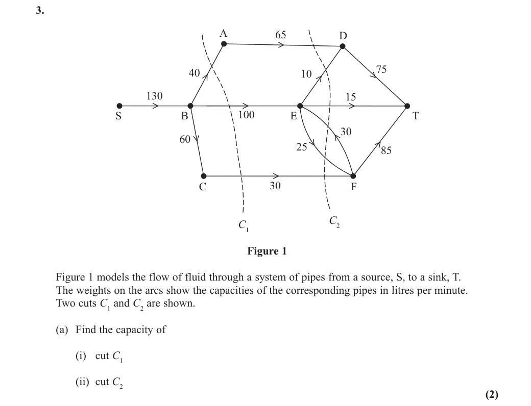
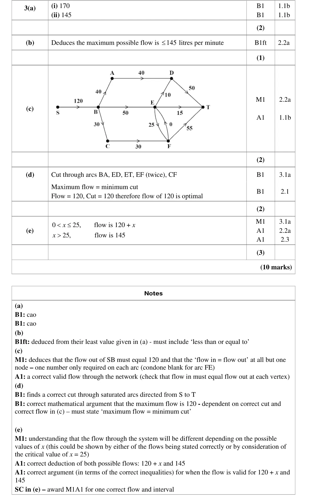
C₁ = 170, C₂ = 145
commonest error was including the 30 on arc FE (directed T to S side) in C₂
June 2018 · AS Paper 2 (Decision 2) · Q3(b)1 mark
Mark scheme (whole question; this part is marked with the orange bar)
Examiner's comment
In (b) most students realised that the maximum flow through the system was linked to the smaller of the two values found in (a) but many did not explicitly state that the maximum possible flow is less
Key points from the mark scheme and examiner's report
maximum flow ≤ 145 litres per minute
must say 'less than or equal to', many gave just 145
June 2018 · AS Paper 2 (Decision 2) · Q3(c)2 marks
Mark scheme (whole question; this part is marked with the orange bar)
Examiner's comment
In part (a) nearly all students correctly calculated the value of both cuts with the most common error being the inclusion of the 30 (from arc FE) in the capacity of cut C2. In (b) most students realised that the maximum flow through the system was linked to the smaller of the two values found in (a) but many did not explicitly state that the maximum possible flow is less than or equal to 145 litres per minute. Even though (c) specifically told students that they did not have to apply the labelling procedure to find a flow of 120 litres per minute from S to T many still did so. Of those students that realised that 120 must flow along SB most went on to show a correct flow. Students are reminded of the following two points when showing a flow on a diagram. There should only be one number on each arc and all arcs should be assigned a value (even if this value is zero). Both of these points were condoned by examiners this session but this may not be so in the future. Part (e) discriminated well and while many students correctly deduced one of the two maximum possible flows through the system very few could give both flows together with the corresponding range of possible values of x.
Key points from the mark scheme and examiner's report
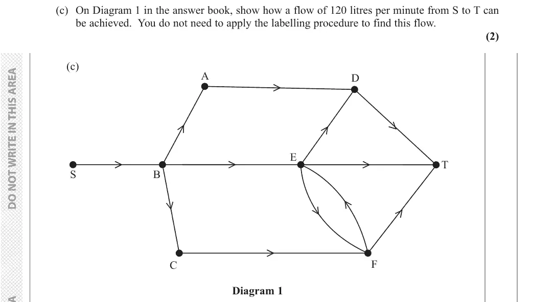
120 must flow along SB with flow in = flow out at every vertex
no labelling procedure needed though many used it anyway
June 2018 · AS Paper 2 (Decision 2) · Q3(d)2 marks
Mark scheme (whole question; this part is marked with the orange bar)
Examiner's comment
In part (a) nearly all students correctly calculated the value of both cuts with the most common error being the inclusion of the 30 (from arc FE) in the capacity of cut C2. In (b) most students realised that the maximum flow through the system was linked to the smaller of the two values found in (a) but many did not explicitly state that the maximum possible flow is less than or equal to 145 litres per minute. Even though (c) specifically told students that they did not have to apply the labelling procedure to find a flow of 120 litres per minute from S to T many still did so. Of those students that realised that 120 must flow along SB most went on to show a correct flow. Students are reminded of the following two points when showing a flow on a diagram. There should only be one number on each arc and all arcs should be assigned a value (even if this value is zero). Both of these points were condoned by examiners this session but this may not be so in the future. Part (e) discriminated well and while many students correctly deduced one of the two maximum possible flows through the system very few could give both flows together with the corresponding range of possible values of x.
Key points from the mark scheme and examiner's report
cut through BA, ED, ET, EF (twice), CF of capacity 120 through saturated arcs
must state maximum flow = minimum cut
June 2018 · AS Paper 2 (Decision 2) · Q3(e)3 marks
Mark scheme (whole question; this part is marked with the orange bar)
Examiner's comment
Part (e) discriminated well and while many students correctly deduced one of the two maximum possible flows through the system very few could give both flows together with the corresponding range of possible values of x.
Key points from the mark scheme and examiner's report
120 + x for 0 < x ≤ 25 and 145 for x > 25 (cut C₂ limits)
very few gave both flows with the correct ranges
Find an Edexcel Further Maths tutor
Stuck on this? Book a trial lesson with our Further Maths tutor.